
User's Manual Part 2a

Hardware Installation Guide Installing the BSDU
02030311-05 Airspan Networks Ltd. 5-9
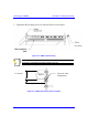
5.7. Daisy-Chaining BSDUs
You can daisy chain up to four BSDUs at each base station. When you daisy chain
BSDUs, you need to connect the 100Base-T ports between BSDUs using a
crossover cable.
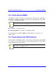
! Connector: 8-pin RJ-45
! Cable: RJ-45-to-RJ-45 crossover
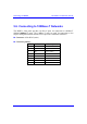
! Connector pinouts: The following table describes the pinouts of the RJ-45
connectors on opposite sides of the crossover cable:
RJ-45 (one end) RJ-45 (other end)
Pin Name
Description
Pin
1 Tx+ Transmit Data+ 3
2 Tx- Transmit Data- 6
3 Rx+ Receive Data+ 1
4 NC Not connected 4
5 NC Not connected 5
6 Rx- Receive Data- 2
7 NC Not connected 7
8 NC Not connected 8
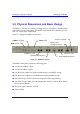
To daisy-chain BSDUs:
1. On the first BSDU, connect the RJ-45 connector, on one end of the crossover
cable, to one of the two 100Base-T ports (labeled 100Base-T 1 or 100Base-T 2)
located on the BSDU’s front panel (see Figure 5-5).
2. On the second BSDU, connect the RJ-45 connector, at the other end of the
crossover cable, to one of the BSDU’s 100Base-T ports (labeled 100Base-T 1 or
100Base-T 2) located on the BSDU’s front panel (see Figure 5-5).
3. If there are additional BSDUs, simply continue connecting the BSDUs using the
100Base-T ports (see Figure 5-5).