
User's Manual


Hardware Installation Manual Installing the BSDU
02030311-03 Airspan Networks Ltd. 5-7
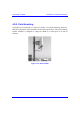
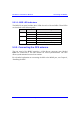
5.3.1.1. BSR LED indicators
The BSDU front panel includes three LEDs for each of the six BSRs. These LEDs
are described in the following table:
LED LED Status
Meaning
On Ethernet activity is detected
Act
Off No Ethernet activity is detected
On Physical link exists between devices
Link
Off No physical link exists between devices
On Current is supplied to the port
Power
Off Port is disabled by software, or port failure
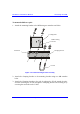
5.3.2. Connecting the GPS antenna
The rear panel of the BSDU provides a 15-Pin D-type connector port—labeled
GPS—for connection to the GPS antenna for clock synchronization. The GPS
allows synchronization between base stations.
For a detailed explanation on connecting the GPS to the BSDU port, see Chapter 6,
“Installing the GPS”.