
User's Manual


Hardware Installation Manual Installing the BSR
02030311-03 Airspan Networks Ltd. 4-7
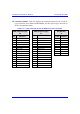
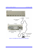
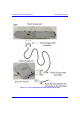
! Connector pinouts: Table 4-2 displays the connector pinouts for the 15-pin D-
type connectors at the BSR and SDA/BSDU, and the 9-pin D-type connector at
the PC management station.
Table 4-2: Y-cable connector pinouts for BSR serial cable connection
SPR (15-pin D Type)
P1
SDA (15-pin D Type)
J1
PC (RS-232)
J2
Pin Function
Pin
9-Pin Function
1 0 VDC 1 0 VDC 1
2 +48 VDC 2 +48 VDC 2 Tx
3 Ethernet Tx+ 3 Ethernet Tx+ 3 Rx
4 Ethernet Tx- 4 Ethernet Tx- 4
5 Ethernet Rx+ 5 Ethernet Rx+ 5 GND
6 Ethernet Rx- 6 Ethernet Rx- 6
7 Ho
p
S
y
nc+ 7 Ho
p
S
y
nc+ 7
8 Ho
p
S
y
nc- 8 Ho
p
S
y
nc- 8
9
N
C 9
N
C9
10
N
C 10
N
C
11
N
C 11
N
C
12
N
C 12
N
C
13
N
C 13
N
C
14 RS232 Rx 14
N
C
15 RS232 Tx 15
N
C