
User's Manual


Hardware Installation Manual Cable Crimping
02030311-03 Airspan Networks Ltd. B-11
3. Trim the centre conductor back to 5.5 mm from the end of the dielectric. Use the
cable shears provided and not the side cutters.
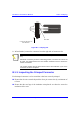
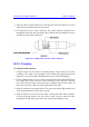
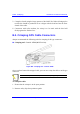
4. Fit centre pin on to the centre conductor. The centre conductor should be seen
through the inspection hole (see Figure B-7). Ensure that the shoulder of the pin
is butted up to the cable’s dielectric.
Figure B-7: Fitting center pin onto center conductor
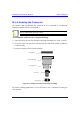
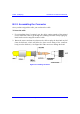
B.2.3. Crimping
To crimp the GPS connector:
1. Using an Erma tool and 29207 die, small aperture, crimp centre pin to centre
conductor. The crimp section should be just be below the inspection hole (see
Figure B-7). Do not crimp the shouldered section as it will cause flashing.
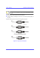
2. Fit the connector body over the centre pin and between the braid and dielectric
(see Figure B-6). Do not trap any of the braid between the dielectric and back
face of the connector body. If the connector is supplied with a nylon washer, fit
this to the rear of the connector before application to the cable.
3. Push the connector body firmly home. The centre pin should align with the end
of the internal diameter of the connector body.
4. Push the ferrule up to the end of the cable, covering the braid. There should be
no braid showing between the end of the ferrule and the connector body.
Rotating the ferrule may rectify this, if not trim the braid slightly to suit.