
User's Manual


Hardware Installation Manual Installing and Configuring the IDR
02030311-03 Airspan Networks Ltd. 10-17
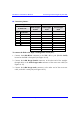
! Connector pinouts:
Straight-through cable
Crossover cable
6-Pin RJ-11
9-Pin D-type
female
9-Pin D-type
male
9-Pin D-type
male
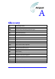
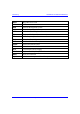
Pin Function
Pin Pin Pin
1 RX 2 4 3
2
N
ot connected - - -
3
N
ot connected - - -
4
N
ot connected - - -
5 GND 5 1 5
6 TX 3 3 2
- - -
- - -
- - -
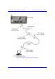
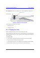
To connect the IDR to the WipLL management station (PC):
1. Connect the 6-Pin RJ-11 connector to the IDR’s RJ-11 port (labeled Serial)
located on the IDR’s front panel (see Figure 10-12).
2. Connect the 9-Pin D-type female connector, at the other end of the straight-
through cable, to the 9-Pin D-type male connector of the cross-over cable (see
Figure 10-12).
3. Connect the 9-Pin D-type male connector, at the other end of the cross-over
cable, to the PC’s serial port (see Figure 10-12).