
User's Manual


Installing and Configuring the IDR Hardware Installation Manual
10-16 Airspan Networks Ltd. 02030311-03
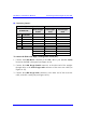
10.3.1. Power LEDs
The IDA provides a power LED indicator, labeled Power, which indicates whether a
power supply exists. The Power LED is located on the front panel of the IDR
chassis.
LED Color Status Meaning
On
The SDA receives power
supply
Power
Red
Off No power received
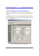
10.4. Configuring the IDR
To perform IDR initial configuration, you need to connect the IDR’s RJ-11 port to
the serial port of a PC running the WipLL network management application (i.e.,
WipConfig).
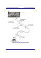
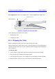
10.4.1. Connecting to a PC
The IDR provides a serial connection to a PC. The IDR’s RJ-11 port labeled Serial,
located on the front panel, connects to the serial port of a PC via a cable with an RJ-
11 connector on the one end, and a 9-Pin D-type connector on the other (i.e., a direct
serial cable connection-DCC).
! Connector:
! 6-Pin RJ-11 male to IDR
! 9-Pin D-type male to PC adapter
! Cable:
! Straight-through cable with 6-Pin RJ-11 male on one end and 9-Pin D-type
female on the other (Connects between IDR and crossed-over cable)
! Cross-over cable with 9-Pin D-type male on one end and 9-Pin D-type
female on the other (connects straight-through cable to PC)