
Installation Guide


Basic Design of Devices Hardware Installation Guide
6-6 Airspan Networks Inc. 02030311-08
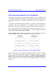
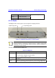
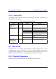
Figure 6-3: BSDU rear panel
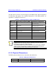
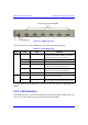
The table below describes the BSDU's ports on the front and rear panels.
Table 6-5: List of BSDU ports
Panel Label Port Interface
100Base-T
RJ-45 (two)
100BaseT interface with provider's backbone
(WAN), and for BSDU and BSRs management
interface (if 10Base-T ports are looped)
SYNC
RJ-45 (two) Synchronization between BSDUs
Monitor
9-pin D-type female BSDU serial interface
10Base-T
RJ-45 (two)
BSDU management (port #2) and management
to BSRs connected to BSDU (port #1)
Management
9-pin D-type male
Base Station Power System (BSPS) remote
management interface using WipManage
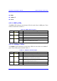
Front
48 VDC
Power receptacle Connecting DC power supply from, e.g. BSPS
GPS
15-pin D-type
Connecting a Global Positioning System (GPS)
antenna for synchronization
Rear
BSR
15-pin D-type (six)
Interfacing with BSRs, providing BSRs with DC
power, Ethernet connection, and synchronization
A 5-mm diameter-grounding lug is present on the rear panel for grounding the
BSDU.
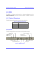
6.2.3. LED Indicators
The BSDU provides various LED indicators located on the BSDU's front panel (see
Figure 6-2). These LEDs are grouped under the following labels:
15-pin D-type ports for BSRs
15-pin D-type for GPS
Grounding lug