
Installation Guide

Hardware Installation Guide Radio Site Planning
02030311-08 Airspan Networks Inc. 5-7
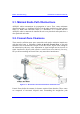
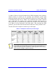
(RSS) to determine the signal strength received from the BSR, and to precisely align
the SPR/IDR for maximum signal strength.
You need to orientate (up/down, left/right) the SPR/IDR until the maximum RSSI
levels are achieved, and then secure the SPR/IDR. For short links you can expect an
RSSI of –60 dBm or better. For longer links, an RSSI of –75 dBm is acceptable.
Any RSSI of less than –80 dBm may be too weak for the radios to reliably
communicate.
Airspan offers various tools for measuring RSS (check with your Airspan
representative regarding cost and supply):
SPR:
RSS LED adapter (see Part II, Chapter 17, "Antenna Alignment using RSS
LED Adapter")
WipConfig program (see Appendix F, "Evaluating Link Quality")
IDR: built-in RSSI LEDs (see Part III, Chapter 24, " Antenna Alignment Using
RSS LEDs")
5.8. Considerations when Using External
Antennas
Notes:
1) To avoid unnecessary RF cable loss, use short-length cables and with low
attenuation.
2) Antennas should have a VSWR of less than 1:1.5.
3) Ensure BSR and SPR/IDR use the same antenna polarity.
4) When using an omni-directional antenna, choose a type providing a wide
vertical beam width (of at least 8°) to allow connection of closer CPEs.
5) Antenna must be DC grounded.
5.8.1. Cable Loss
Airspan's ASWipLL radios provide transmit power compensation for power
attenuation caused by cable loss (in cable connecting to external antenna). Cable loss