
Installation Guide

Radio Site Planning Hardware Installation Guide
5-6 Airspan Networks Inc. 02030311-08
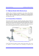
The Rx value must be higher than the receiver sensitivity for communication link to
succeed.
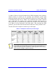
Example: Frequency =2.4 GHz; Tx power output = 27 dBm; Tx and Rx cable loss =
0 dB; Tx antenna gain = 11 dBi; Rx antenna gain = 15 dBi; distance between sites =
6 km; Receiver sensitivity = -75 dBm.
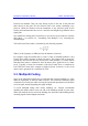
Transmit output power 27 dBm
Cable loss (negative value) 0 dB
Transmit
Antenna gain 11 dBi
Propagation
Free space loss (negative value)
32.44 + 20log(6 km) + 20log(2400 MHz)
-116 dB
Antenna gain 15 dBi
Receive
Cable loss (negative value) 0 dB
Minimal received signal Rx = -63 dBi
Therefore, received signal power is EIRP – path loss + receive = 38 dBm – 116 dB +
15 dBi = -63 dBm. In conclusion, the received signal power is above the device's
sensitivity threshold (-75); thus a communication link should succeed.
Notes:
1) ASWipLL can operate in 2-, 4-, and 8-level FSK with signal strengths (i.e.
receiver sensitivity) of greater than -90, -83, and -75 dBm, respectively.
2) These link budget rules are theoretical. It represents the maximum
achievable for a system. In reality we have interferences (other WLAN
networks, bluetooth), industrial noise (microwave ovens), atmospheric losses
(air moisture, scattering, refraction), badly pointed antenna, reflexions,... that
will affect performances. Thus, It is necessary to take a sufficient security
margin on large distances.
3) Normally, a higher margin is desirable due to fluctuation in received power
as a result of signal fading.
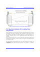
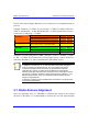
5.7. Radio Antenna Alignment
Once the subscriber unit (i.e. SPR/IDR) is installed and aimed in the general
direction of the BSR, it is recommended to measure the received signal strength