ASWipLL and AS3010 Systems Wireless IP-Based Local Loop System Release 4.
The ASWipLL product bears the CE marking. This CE marking demonstrates ASWipLL's full compliance with applicable European Union (EU) directives: The ASWipLL product bears the Underwriters Laboratories (UL) marking, demonstrating full compliance with UL's safety requirements: ASWipLL products also bear the Federal Communications Commission (FCC) marking, demonstrating compliance with FCC Part 15 regulations. Pub. Rev.
2 Safety Guidelines This chapter outlines safety guidelines when installing the ASWipLL system. Warning: The user and the installer should be aware that changes and modifications not expressly approved by Airspan Networks could void the user’s authority to operate the equipment. Warning: Never install equipment that is damaged. Warning: Only qualified personnel should be allowed to install, replace, and service the ASWipLL equipment. 02030311-07 Airspan Networks Inc.
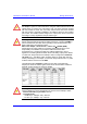
Safety Guidelines Hardware Installation Guide 2.1. ASWipLL Radios and Third-Party External Antennas Warning: Do not connect and disconnect antennas while the power is on. This can cause irreversible device damage. Warning: The digital portion of the transceiver has been tested and found to comply with the limits for a Class B digital device, pursuant to part 15 of the FCC rules. These limits are designed to provide reasonable protection against harmful interference in a residential installation.
Hardw are Installation Guide Safety Guidelines Warning: For unlicensed bands, it is the responsibility of the person installing the ASWipLL system to ensure that when using the outdoor antenna kits in the United States (or where FCC rules apply), that only those antennas certified with the product are used. The use of any antenna other than those certified with the product is expressly forbidden in accordance with FCC rules CFR47 part 15.204.
Safety Guidelines Hardware Installation Guide Warning: To avoid RF interference between BSRs operating in the 700 MHz where four BSRs are installed at a Base Station, a 1-meter separation must be provided between the BSRs' antennas operating in the lower frequencies (i.e. 711.5 and 714.5 for 1 Msps mode; 712 and 714 for 1.33 Msps mode) and the BSRs' antennas operating in the upper frequencies (i.e. 741.5 and 744.5 for 1 Msps mode; 742 and 744 for 1.33 Msps mode).
Hardware Installation Guide Safety Guidelines 2.2. Electrical Safety Guidelines Warning: Connect the power only after all network and antenna cable connections are performed. Powering the device before connecting, for example, the external antenna, can lead to irreversible device damage. Warning: To prevent short-circuiting and electrical shocks, cables with exposed ends (i.e. not yet crimped) should be covered with protective polythene bags during external cable installation processes. 2.2.1.
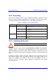
Safety Guidelines Hardware Installation Guide 2.2.2. Grounding Only certain ASWipLL devices require additional grounding. ASWipLL devices that do not require additional grounding have grounding at the main supply outlet. The following table lists the ASWipLL devices’ grounding requirements. Table 2-1: ASWipLL grounding requirements Site Base Station CPE ASWipLL device Grounding BSR Through the mains (via BSDU) i.e.
Hardware Installation Guide Safety Guidelines However, for geographical areas that have above normal lightening activity, Airspan can supply a surge protector composed of a 15-pin D-type adapter with a grounding wire. 2.3. Cabling Warning: The maximum cable length between the radio transmitters (i.e. BSR and SPR) and terminating equipment is 100 meters. Warning: Cables with exposed ends (i.e. not yet crimped) should be covered with protective polythene bags during external cable installation processes.
Safety Guidelines Hardware Installation Guide ! Plastic ties and wraps are to be used to secure cables at regular intervals to trays, guides, and mounting pole/bracket. Ensure all trimmed ends are disposed of safely and at regular intervals. ! Data cables of less than 20 pairs shall be mixed in bundles not exceeding 50 mm in diameter. ! Ensure cables are not trapped in cabinet doors, by slide-in equipment or support metalwork.
Hardware Installation Guide Safety Guidelines ! Silicone sealant should be used to plug any holes on both internal and external wall surfaces once cables are in place. ! Cables not housed in conduits must be placed in a manner to avoid a trip hazard. (Avoid trailing wires across passageways.) 2.3.2. Labeling The following labels are required to be fitted to ASWipLL equipment: ! Voltage Warning ! High Earth Leakage Current ! Signal Cable Designation 2.3.2.1.
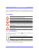
Safety Guidelines Hardware Installation Guide 2.3.2.2. High Earth Leakage Current If equipment earth leakage current exceeds 3.5 mA, a warning label as shown in Figure 2-1 must be fitted to the rear of the main power rack alongside the AC inlet terminal block. WARNING HIGH LEAKAGE CURRENT Earth connection essential Before connecting supply Figure 2-1: Warning label if earth leakage current exceeds 3.5 mA 2.3.2.3.