
Installation Guide

AirHarmony-4200 DC (Internal Filters) Installation Guide
UGD-D01196 Airspan Commercial and Internal Use 37
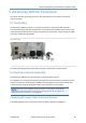
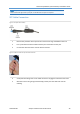
1. Attach, connect and secure the RF cable between the external antenna and the
appropriate RF connection on the top of the External Duplexers.
Caution: Antennas must be connected and attached before AirHarmony is powered on.
Caution: Power down AirHarmony prior to disconnecting antenna.
Note:
First Sector/Carrier antenna should be connected to the top antenna ports.
Second Sector/Carrier antenna should be connected to the top antenna ports.
Antennas for each sector can be either Directional or Omni.
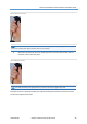
2. Weather-proof the RF connections.
Note: The above is also applicable for replacement assembly.
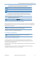
Weather-proofing the Antenna Connections
Weather-proofing of all the connections is required. This is done with a layer of self-amalgamating
tape followed by an over layer of PVC tape. The weather-proofing is best done at this stage to give
easier access to the connections.
Note: Weather-proofing is best done at the assembly stage to give easier access to the
connections. Weather-proofing is to be done to all RF connectors.
Verify the RF connectors are completely weather-proof.
5.3 Cable Connections
Note: The following images are for illustration purposes only. The actual tools or
hardware may differ according to manufacturer.
Copper Ethernet Cable Assembly
The following demonstrates the recommended assembly instructions, hardware and tool
requirements for the proper Ethernet cable assembly of the Ethernet Category 5e (enhanced)
(CAT5e) cable used by Airspan products.
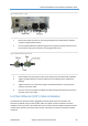
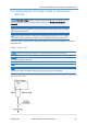
The Ethernet cable is connected using a standard RJ45 connector protected by a harsh environment
protective casing.
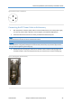
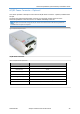
The Copper Ethernet cable is connected to the AirHarmony-4200 DC using a Gland connector
assembled on the bottom panel of the unit, as shown below.