NewLife® Intensity 10 Oxygen Concentrator Service Manual AirSep Corporation • 401 Creekside Drive • Buffalo, NY 14228-2085 USA Telephone: (716) 691-0202 • 24-Hour Fax: (716) 691-4141 • www.airsep.
Expedited Product Warranty Check service is always at your fingertips with AirSep: http://www.airsep.com/Support/Warranty_Information.aspx OR In the US or Canada, dial 866-873-9277 AirSep® is a registered trademark of AirSep Corporation. • NewLife® is a trademark of AirSep Corporation.
Table of Contents Section 1.0 Introduction 1.1 Equipment Provider Responsibility 1 1.2 Important Notice and Symbol Explanations 2 1.3 Functional Specifications 4 2.1 Description of Operation 5 2.2 Operation Check 5 2.3 Alarm System 5 2.3.1 2.3.2 6 6 Section 2.0 Operation Check and Oxygen Concentration Test Start Up/Battery Test Power Failure Alarm Test 2.4 Oxygen Concentration Test and Specification 6 3.1 Instructions 7 3.2 Routine Maintenance by the Patient 7 Section 3.
Section 5.0 Main Components 5.1 Components 10 5.2 Cabinet Removal 10 5.2.1 5.2.2 5.2.3 5.2.4 5.2.5 5.2.6 10 10 10 10 10 10 5.3 5.4 5.5 5.6 5.7 Removing Side Panel(s) Removing Back Panel Removing Lower Front Panel Removing Control Panel Superstructure Caster Replacement Compressor 11 5.3.1 5.3.2 11 12 Compressor Replacement Capacitor Replacement Solenoid Valves 12 5.4.1 5.4.2 12 12 Feed/Waste Valve Replacement Solenoid Valve Coil Replacement Sieve Beds 13 5.5.
Section 6.0 Troubleshooting 6.1 Operating Pressure Test 20 6.1.1 6.1.2 20 20 High Operating Pressure Low Operating Pressure 6.2 General Troubleshooting 21 6.3 Troubleshooting Chart 22 6.
1.0 Introduction 1.1 Equipment Provider Responsibility All Equipment Providers of the NewLife® Intensity 10 Oxygen Concentrator must assume responsibilities for handling, operational check-out, patient instruction, and oxygen concentration checks. These responsibilities are outlined below and throughout this manual. As an Equipment Provider, you must do all of the following: § Inspect the condition of each NewLife Intensity 10 unit immediately upon delivery to your business location.
1.2 Important Notice and Symbol Explanations As you read the manual, pay special attention to the WARNING, CAUTION, and NOTE messages. They identify safety guidelines or other important information as follows: Describes a hazard or unsafe practice that can result in severe bodily injury or death. Describes a hazard or unsafe practice that can result in minor bodily injury or property damage. Provides information important enough to emphasize or repeat.
Method for disposing of waste: All waste from the NewLife Intensity 10 (patient circuit, etc.) must be disposed of using appropriate methods. Method for disposing of the device: In order to preserve the environment, the concentrator must only be disposed of using the appropriate methods. Conformity with EN 60-601 (§ 6.8.
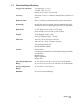
1.3 Functional Specifications Oxygen Concentration: 2-9 LPM: 92% +3.5/-3% 10 LPM: 90% +5.5/-3% (Based on 70°F [21°C] at sea level) Accuracy: Flowmeter ± 10% or ± 200ml of indicated flow, whichever is greater. Response Time: Allow 5 minutes to attain maximum oxygen concentration. Positioning: Operate the unit in an upright position, maintaining at least 12 inches (30.5cm) of open space on all sides for ventilation. Dimensions: 27.5 in. high x 16.5 in. wide x 14.5 in. deep (69.9 cm high x 41.
2.0 Operational Check and Oxygen Concentration Test 2.1 Description of Operation Air is drawn into the NewLife Intensity 10 Oxygen Concentrator through an external air intake gross particulate filter. Before this air enters the compressor, it passes through the unit’s suction resonator which, quiets the compressor’s suction sound. Pressurized air then exits the compressor and passes through a heat exchanger. The heat exchanger reduces the temperature of the compressed air.
oxygen monitor detects lower than therapeutic levels of oxygen concentration. The alarm remains on until you correct the alarm condition or you set the I/0 power switch to the “0” position. Refer to Section 6.0 for a list of probable alarm causes. 2.3.1 Start Up/Battery Test Each time the NewLife Intensity 10 unit is turned on, an alarm should sound for approximately five seconds.
3.0 Patient Instructions 3.1 Instructions It is important that patients thoroughly understand how to operate the AirSep NewLife Intensity 10 unit. This enables proper treatment, as prescribed by a licensed health care provider/physician. If patients experience any discomfort or the unit alarms, they must notify their licensed health care provider/physician immediately. You, as the Equipment Provider, are responsible to see that each patient receives the Patient Manual.
4.0 Provider Instructions 4.1 Instructions To ensure that the unit’s output of oxygen is within specification, you must perform a test of the oxygen concentration. Test the unit upon delivery to a patient and at periodic intervals. Equipment Providers need to establish and implement a protocol to check oxygen concentration. (Refer to Section 2.4.) AirSep does not require preventative maintenance on the concentrator.
4.1.5 Recording Maintenance As the Equipment Provider, you can record all routine maintenance and repairs performed on the NewLife Intensity 10 unit, including hours and dates of service. A History Record label is located on the side panel inside the unit. Keep this record current to avoid unnecessary replacement of parts (i.e., intake filter and battery). Electrical shock hazard.
5.0 Main Components 5.1 Components The design of the AirSep NewLife Intensity 10 Oxygen Concentrator allows for easy access and removal of most components. This allows you to perform repair and replacement of parts with minimal time and effort. To prevent accidental electrical shock or burn, be sure to set the unit’s I/0 power switch to the “0” position and disconnect the power cord of the unit from the electrical outlet before you service the NewLife Intensity 10 Oxygen Concentrator.
5.3 Compressor The compressor is the “pump” within the oxygen concentrator that pushes the room air into the bottom of the sieve beds. This allows oxygen to flow out of the top of the sieve beds in the NewLife Intensity 10 unit. Two different aspects of the compressor cause concern: the output and the sound level. Output Compressor output refers to how much compressed air the compressor can produce. This depends upon the model of the compressor, stroke size, bore size, and cup seal condition.
5.3.2 Capacitor Replacement The capacitor starts the compressor. If the compressor cannot start, the capacitor may be defective and require replacement. To replace the capacitor, follow the steps below: 1. Set the unit’s I/0 switch to the “0” position and disconnect the power cord. 2. Remove the side and lower front panels. 3. Disconnect the two leads to the capacitor and slide capacitor out of the tiewrap holding it in place. 4.
b. Feed/waste coil = 850ohms +/- 10% 2. 220-240VAC units a. EQ coil = 4,300ohms +/- 10% b. Feed/waste coil = 3,100ohms +/- 10% You can also determine which coil is not operating by checking each valve to see if it becomes energized (magnetized) during unit operation. To check for coil operation, follow the steps below: 1. Remove plastic cap securing the valve coil to the valve stem. (Do not remove coil). 2.
If replacement is necessary, you must replace both sieve beds at the same time. Sieve Bed Removal To remove sieve beds, follow the steps below: 1. Set the unit’s I/0 switch to the “0” position and disconnect the power cord. 2. Remove the side and back panels. 3. Cut the tie-wrap and disconnect green tubing at each elbow fitting located on the top of the sieve beds. 4. Remove the 9/16-inch compression fitting from the bottom of each sieve bed. 5.
A green light that fails to illuminate indicates a disconnected or faulty solenoid coil or an electrical malfunction in that valve circuit. The two vertical red lights indicate high and low pressure. Consult the troubleshooting chart in Section 6.0 to determine when to replace the printed circuit board. The Printed Circuit Boards (PCBs) contain components that are sensitive to electrostatic discharge (ESD) and can damage the board if not handled properly.
4. 5. 6. 7. 8. 9. 10. Remove the 2nd stage intake resonator, which is held in place by Velcro. Remove the securing nut that holds the product tank to the superstructure. (This securing nut is located in the top right area of the compressor compartment). Remove the screws that hold the control panel to the superstructure. It is not necessary to fully remove the control panel. It is only necessary to create enough room to allow the product tank to be removed from the unit.
5.9.2 Product Regulator Cleaning or Rebuilding Clean or rebuild the product regulator if the regulator cannot be adjusted for lockout. 1. Set the unit’s I/0 switch to the “0” position and disconnect the power cord. 2. Remove the right side panels and back panels. 3. Use large pliers to unscrew the bonnet of the product regulator, which contains a large spring. Adjust the product regulator fully counter-clockwise to unload the spring. This makes disassembly and reassembly easier. 4. Remove the diaphragm.
I/0 Power Switch Installation Follow the removal procedure for the I/0 power switch in reverse order to install a new power switch. 1. Be sure to reinstall the new switch properly with the orientation of the “0” on the switch located on the bottom when finished. 2. Same side wire connections of power switch can be made to either terminal. 5.12 Buzzer Replacement 1. 2. 3. 4. 5. Set the unit’s I/0 switch to the “0” position and disconnect the power cord. Remove the left side panel.
3. 4. 5. 6. Open the plastic twist clamps. Cut the tie-wraps (located near the power cord push-on connectors). Disconnect the white power cord lead from the I/0 switch lead. Disconnect the black power cord lead from the top terminal on the circuit breaker. 7. Locate strain relief inside power cord receptacle. Press both ends together with pliers while pushing power cord from the back to remove power cord. Pull the power cord through the opening on the power cord receptacle. 8.
6.0 Troubleshooting 6.1 Operating Pressure Test Testing the operating pressure is a useful diagnostic tool when a concentrator produces low oxygen concentration and requires servicing. Units functioning normally do not require operating pressure tests. Use the following procedure to test the operating pressure of the unit: 1. Set the unit’s I/0 power switch to the “0” position, and disconnect the power cord. 2. Remove the right side panel. 3.
6.2 General Troubleshooting Before reviewing the troubleshooting chart, the following steps may be useful to isolate any malfunctions: 1. Turn on the concentrator. If the unit does not turn on, refer to the troubleshooting chart. 2. Verify the outlet pressure is 20 psig (138 kPa). If the outlet pressure is not at 20 psig (138 kPa), the product regulator needs to be reset. Refer to Section 5.9. 3. Make sure the unit is cycling properly by: a. observing the flowmeter ball is stable in flowmeter.
6.3 Troubleshooting Chart Problem Unit does not run. Constant audio alarm with I/0 power switch in “I” position. Compressor runs and shuts down periodically. Compressor does not start. I/0 power switch in “I” position, intermittent alarm, and cabinet fan turns. Compressor runs with intermittent low pressure alarm and low oxygen concentration. Probable Cause Solution No power to unit from electrical outlet. Check/restore power to outlet. Unit circuit breaker tripped/faulty.
Problem Compressor runs with intermittent high pressure alarm and low oxygen concentration. Compressor relief valve releases (popping sound) Constant alarm with I/0 power switch in “I” position. Circuit breaker repeatedly trips. Alarm does not sound. Flowmeter fluctuates. Probable Cause Solution Restriction in exhaust muffler. Replace or clean muffler. Faulty solenoid valve. Repair or replace solenoid valve. Faulty circuit board. Replace circuit board. Contaminated sieve beds.
Problem Cabinet fan does not turn. Limited or low flow Low oxygen concentration Probable Cause Solution Faulty electrical connections. Check electrical connections. Faulty cabinet fan. Replace cabinet fan. Restriction in humidifier/tubing. Replace humidifier or tubing. Product regulator set too low. Adjust regulator setting. Leak. Leak test and repair leak. Reduced air intake (suction). Check compressor intake path for obstruction. Clean/remove obstruction. Faulty solenoid valve.
6.4 Tool Kit and Pressure Test Gauge The tools needed for you to properly service the NewLife Intensity 10 unit are listed below: Multi-adjustable pliers, wire cutters, needle-nose pliers, slotted-head screwdriver, Phillipshead screwdriver, ratchet, adjustable wrench, 1-inch deep well socket, 9/16-inch socket, 2inch extension, 7/16-inch combination wrench, 9/16-inch combination wrench, and 5/8inch combination wrench. Pressure test adapter (AirSep p/n: KI057-1).
APPENDIX • Exploded drawings Wiring Diagram – Intensity 10 120V A Wiring Diagram – Intensity 10 220/240V B Control Panel Assembly C Main Structure Assembly D Base and Cabinet Components E Product Tank/Regulator Assembly F Valve Block Assembly G Compressor Assembly H Sieve Bed Assembly I
WIRING DIAGRAM INTENSITY 10 120V A MN134-1 rev B 02/14
WIRING DIAGRAM INTENSITY 10 220/240V B MN134-1 rev B 02/14
ITEM PART NUMBER 1 2 3 4 5 6 7 8 9 10 11 12 BK016-1 CA003-1 CB068-9 CB107-1 CR001-1 CR001-6 F0005-2 F0007-3 F0025-1 F0414-1 F0590-1 F0631-1 DESCRIPTION BRACKET, FLOWMETER, DUAL CABINET, CONTROL PANEL CIRCUIT BOARD, 120V CIRCUIT BOARD, 220V CIRCUIT BREAKER, 120V CIRCUIT BREAKER, 220V FITTING, BRASS, ADAPTER FITTING, OUTLET FITTING, OXYGEN CONNECTOR FITTING, PALNUT, FLOWMETER FITTING, ADAPTER, DEMAND VALVE FITTING, OUTLET BLOCK ITEM PART NUMBER 13 14 15 16 17 18 19 20 21 22 23 FA002-1 FM056-1 HM009-2
ITEM PART NUMBER 1 2 3 4 5 6 7 8 9 10 11 12 13 14 BT001-2 BT002-1 CA214-1 FA002-1 FA003-1 FN022-1 FN022-2 FO002-1 HA001-1 MI161-2 MU089-1 NU003-1 RN020-1 RN027-1 DESCRIPTION BATTERY, HOLDER BATTERY CABINET, SUPERSTRUCTURE FASTENER, TIE-WRAP MOUNT FASTENER, WIRE HARNESS FAN, 120V FAN, 220V FOAM, EQ SPACER, TEMP SWITCH FELT, INTAKE MUFFLER NUT, TERMINAL BLOCK ST RESONATOR, 1 STAGE ND RESONATOR, 2 STAGE ITEM PART NUMBER 15 16 17 18 19 20 21 22 23 24 25 26 27 28 SC002-1 SC001-2 SC002-6 SC003-1 SC004-1 S
ITEM PART NUMBER 1 2 3 4 5 BE186-1R CA034-1 CA036-4 CA201-1 CA254-1 DESCRIPTION BEDS CABINET, BACK PANEL CABINET, SIDE PANEL CABINET, ROLLER BASE CABINET, FRONT PANEL ITEM PART NUMBER 6A 6B 7 8 CD011-2 CD011-4 CS001-1 FI002-1 DESCRIPTION CORD, POWER, US-STYLE CORD, POWER, EUROPEAN –STYLE CASTER FILTER, FOAM BASE AND CABINET COMPONENTS E MN134-1 rev B 02/14
ITEM PART NUMBER 1 2 RG088-1 TA132-1 DESCRIPTION REGULATOR (ONLY) TANK, MIXING, ASSY PRODUCT TANK/REGULATOR ASSEMBLY F MN134-1 rev B 02/14
ITEM PART NUMBER 1 2 3A VA290-3 VA034-1 VA054-1 DESCRIPTION VALVE, BLOCK (ONLY) VALVE, FEED/WASTE REBUILT KIT VALVE, COIL, 120V ITEM PART NUMBER 3B 4A 4B VA117-1 VA001-1 VA001-2 DESCRIPTION VALVE, COIL, 220V VALVE, SOLENOID, 120V VALVE, SOLENOID, 220V VALVE BLOCK ASSEMBLY ITEM PART DESCRIPTION ITEM G PART DESCRIPTION MN134-1 rev B 02/14
NUMBER 1 2 3 4 5 CL007-1 CO306-1R CO306-2R F0045-2 F0627-1 NUMBER CLAMP, HEAT EXCHANGER COMPRESSOR, ASSY, 120V COMPRESSOR, ASSY, 220V FITTING, ELBOW, INTAKE FITTING, ADAPTER, INTAKE 6 7 8 9 10 F0104-1 HX002-2 KI070-1 SC013-2 WA002-14 FITTING, ELBOW, HEAT EXCHANGER HEAT EXCHANGER KIT, SPRING MOUNT SCREW, CLAMP WASHER, CLAMP COMPRESSOR ASSEMBLY ITEM PART DESCRIPTION ITEM H PART DESCRIPTION MN134-1 rev B 02/14
NUMBER 1 2 3 4 5 6 7 8 BE002-4 BE005-2 BE005-3 BE006-1 BE011-4 BE058-1 BE059-1 BE071-1 NUMBER BED, TUBE BEDS, LEFT CAP ASSY, TOP BEDS, RIGHT CAP ASSY, TOP BEDS, CAP ASSY, BOTTOM BEDS, RODS BEDS, BAFFLE BEDS, PISTON ASSY, STATIONARY BEDS, PISTON ASSY, MOVING 9 10 11 12 13 14 15 16 F0001-2 F0105-7 F0134-1 GS017-1 NU001-1 NU040-1 OR001-1 SP006-1 FITTING, ELBOW, TOP CAP FITTING, ADAPTER, BOTTOM CAP FITTING, COMPRESSION NUT GASKET NUT, BOTTOM CAP NUT, TOP CAP O-RING SPRING SIEVE BED ASSEMBLY I MN134-1 re