
Installation Manual

66 440 01 4501 01
Specifications subject to change without notice.
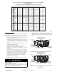
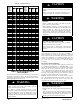
Table 22 – Gas Rate (CU ft./hr)
SEC-
ONDS
FOR 1
REVO-
LUTION
SIZE OF TEST DIAL
SEC-
ONDS
FOR 1
REVO-
LUTION
SIZE OF TEST DIAL
1
Cu
Ft.
2
Cu
Ft.
5Cu
Ft.
1
Cu
Ft.
2
Cu
Ft.
5
Cu
Ft.
10 360 720 1800 55 65 131 327
11 327 655 1636 56 64 129 321
12 300 600 1500 57 63 126 316
13 277 555 1385 58 62 124 310
14 257 514 1286 59 61 122 305
15 240 480 1200 60 60 120 300
16 225 450 1125 62 58 116 290
17 212 424 1059 64 56 112 281
18 200 400 1000 66 54 109 273
19 189 379 947 68 53 106 265
20 180 360 900 70 51 103 257
21 171 343 857 72 50 100 250
22 164 327 818 74 48 97 243
23 157 313 783 76 47 95 237
24 150 300 750 78 46 92 231
25 144 288 720 80 45 90 225
26 138 277 692 82 44 88 220
27 133 267 667 84 43 86 214
28 129 257 643 86 42 84 209
29 124 248 621 88 41 82 205
30 120 240 600 90 40 80 200
31 116 232 581 92 39 78 196
32 113 225 563 94 38 76 192
33 109 218 545 96 38 75 188
34 106 212 529 98 37 74 184
35 103 206 514 100 36 72 180
36 100 200 500 102 35 71 178
37 97 195 486 104 35 69 173
38 95 189 474 106 34 68 170
39 92 185 462 108 33 67 167
40 90 180 450 110 33 65 164
41 88 176 439 112 32 64 161
42 86 172 429 116 31 62 155
43 84 167 419 120 30 60 150
44 82 164 409 124 29 58 145
45 80 160 400 129 28 56 140
46 78 157 391 133 27 54 135
47 76 153 383 138 26 52 130
48 75 150 375 144 25 50 125
49 73 147 367 150 24 48 120
50 72 144 360 157 23 46 115
51 71 141 355 164 22 44 110
52 69 138 346 171 21 42 105
53 68 136 340 180 20 40 100
54 67 133 333
SERVICE AND MAINTENANCE
PROCEDURES
Untrained personnel can perform basic maintenance functions such
as cleaning and replacing air filters. All other operations must be
performed by trained service personnel. A qualified service person
should inspect the furnace once a year.
FIRE, INJURY OR DEATH HAZARD
Failure to follow this warning could result in personal
injury, death and/or property damage.
The ability to properly perform maintenance on this
equipment requires certain knowledge, mechanical skills,
tools, and equipment. If you do not possess these, do not
attempt to perform any service and maintenance on this
equipment other than those procedures recommended in the
Owner’s Manual.
!
WARNING
ENVIRONMENTAL HAZARD
Failure to follow this caution may result in environmental
pollution.
Remove and recycle all components or materials (i.e. oil,
refrigerant, control board, etc.) before unit final disposal.
CAUTION
!
ELECTRICAL SHOCK, FIRE OR EXPLOSION
HAZARD
Failure to follow this warning could result in personal
injury or death, or property damage.
Before installing, modifying, or servicing system, main
electrical disconnect switch must be in the OFF position and
install a lockout tag. There may be more than one
disconnect switch. Lock out and tag switch with a suitable
warning label. Verify proper operation after servicing.
Always reinstall access doors after completing service and
maintenance.
!
WARNING
ELECTRICAL OPERATION HAZARD
Failure to follow this caution may result in improper
furnace operation or failure of furnace.
Label all wires prior to disconnection when servicing
controls. Wiring errors can cause improper and dangerous
operation.
CAUTION
!
General
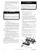
These instructions are written as if the furnace is installed in an
upflow application. An upflow furnace application is where the
blower is located below the combustion and controls section of the
furnace, and conditioned air is discharged upward. Since this
furnace can be installed in any of the 4 positions shown in Fig. 3,
you must revise your orientation to component location
accordingly.
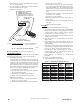
Electrical Controls and Wiring
Each pressure switch is labeled with the reference location (noted
as “COLLECTOR BOX--LPS” or “HOUSING--HPS” on the
switch). The nominal break point of each switch is shown on the
label below the reference location in inches of water column,
“W.C.” The maximum and minimum break point of the switch is
+/-- 0.05 inches of water column from the nominal break point of
the switch. The maximum make point of the switch is 0.10 inches
of water above the maximum break point of the switch.
Example: Nominal break point on pressure switch is 0.68 --in.
W.C. The minimum break point of the switch is 0.63 -- in. W.C.
The maximum break point of the switch is 0.73--in. W.C. The
maximum make point of the switch is 0.83 -- in. W.C.
ELECTRICAL SHOCK HAZARD
Failure to follow this warning could result in personal injury
or death.
There may be more than one electrical supply to the furnace.
Check accessories and cooling unit for additional electrical
supplies that must be shut off during furnace servicing. Lock
out and tag switch with a suitable warning label.
!
WARNING