
Natural Gas to Propane Conversion Instructions
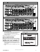
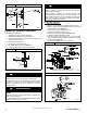
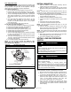
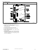
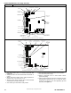
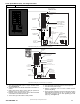
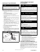
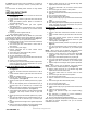

Figure 17 Burner Flame
Burner Flame
Burner
Manifold
A11461
CHECK LOW GAS PRESSURE
SWITCH
The newly installed low gas pressure switch is a safety device
used to guard against adverse burner operating characteristics
that can result from low gas supply pressure. Switch opens at
not less than 6.5 in. w.c. and closes at not greater than 10.2 in.
w.c.
This switch also prevents operation when the propane tank level
is low which can result in gas with a high concentration of
impurities, additives, and residues that have settled to the
bottom of the tank. Operation under these conditions can cause
harm to the heat exchanger system. This normally open switch
closes when gas is supplied to gas valve under normal
operating pressure. The closed switch completes control circuit.
Should an interruption or reduction in gas supply occur, the gas
pressure at switch drops below low gas pressure switch setting,
and switch opens. Any interruption in control circuit (in which low
gas pressure switch is wired) quickly closes gas valve and stops
gas flow to burners. When normal gas pressure is restored, the
system must be electrically reset to re- establish normal heating
operation.
Before leaving installation, observe unit operation through two
complete heating cycles. During this time, turn gas supply to gas
valve off just long enough to completely extinguish burner flame,
then instantly restore full gas supply. To ensure proper low gas
pressure switch operation, observe that there is no gas supply
to burners until after hot surface igniter begins glowing.
LABEL APPLICATION
1. Fill in Conversion Responsibility Label 344674- 204 and
apply to Blower Access Door of furnace. Date, name, and
address of organization making this conversion are
required. (See Figure 18)
2. Attach Conversion Rating Plate Label 344674- 201 to
outer door of furnace. (See Figure 6)
3. Apply Gas Control Conversion Label: Use Gas Control
Conversion Label 344674- 202 (See Figure 19) Do not
use 344674- 203 which is similar.
4. Replace control access door, blower access door and
outer door of furnace.
CHECKOUT
1. Observe unit operation through two complete heating
cycles.
2. See Sequence of Operation in furnace Installation, Start-
Up, and Operating Instructions.
3. Set room thermostat to desired temperature.
Figure 18
Gas Conversion Responsibility Label
A190074
Figure 19 Gas Control Conversion Label
A190075
Copyright 2019 CAC / BDP D 7310 W. Morris St. D Indianapolis, IN 46231
Manufacturer reserves the right to c hange, at any time, specifications and designs without notice and without obligations.
Catalog No: AG- KN018SNP- 01 REV C
Replaces: AG- KN018SNP- 01
Edition Da te: 06/19