
Installation Manual

484 01 3905 03 5
Specifications subject to c hange without notice.
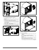
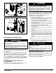
Unbend tab as
shown, 4 places.
A13064
Figure 8 - Hori zontal Lef t Instal lation
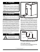
Self- Tapping Screws
A13066
Figure 9 - Hori zontal Lef t Instal lation
REFRIGERANT LINE CONNECTIONS
!
WARNING
PERSONAL INJURY HAZARD
Failure to follow this warning could result in personal injury.
Wear eye protection.
Coil is factory charged with 15 psi nitrogen. The c oil is under
pressure and TXV screen is in place behind liquid line plug. DO
NOT remove liquid line plug first, always remove the suction
line plug first to depressurize the coil.
NOTE: Factory nitrogen charge may escape past rubber plugs
during storage. This does not indicate a leaking coil nor warrant
return of the coil.
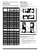
Size and install refrigerant lines according to information provided
with outdoor unit. Coil connection tube sizes are shown in
Table 1. Route refrigerant lines to the coil in a manner that will not
obstruct service access to the unit or removal of the filter.
Do not use damaged, dirty, or contaminated tubing because it
may plug refrigerant flow- control device. ALWAYS evacuate
the coil and field - supplied tubing before opening outdoor unit
service valves.
CONNECT REFRIGERANT, LIQUID, and
SUCTION LINES
For matched and mismatched systems, use line sizes
recommended in outdoor unit Installation Instructions.
UNIT OR PROPERTY DAMAGE HAZARD
Fail ur e to foll ow t hi s cauti on may r esul t in proper ty damage.
Take precauti ons to ensur e Alum i num tubes do not come in
dir ect contact or allow for condensate run of f wit h a
dissi m i l ar metal . Dissim i l ar metals can cause galvanic
corr o si on and possibl e pr ematur e failure.
CAUTION
!
The c oil can be connected to outdoor units using field - supplied
tubing of refrigerant grade. Always evacuate tubing and reclaim
refrigerant when making connections or flaring tubing. Leak
check connections before insulating entire suction line.
See Table 1 for coil connection tube size.
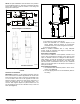
1. Remove cabinet access door.
2. Remove rubber plugs, suction plug then liquid plug, from
coil stubs using a pulling and twisting motion. Hold coil
stubs steady to avoid bending or distorting.
3. Remove tubing plate with rubber grommets and slide plate
with grommets onto the refrigerant lines (field line- set),
away from braze joints.
4. Fit refrigerant lines into coil stubs. Wrap a heat sinking
material such as a wet cloth behind braze joints.
5. Wrap TXV and nearby tubing with a heat- sinking material
such as a wet cloth.
6. Use 1/2 psig Nitrogen purge in the suction and out the the
liquid line.
7. Braze using a Sil- Fos or Phos- copper alloy. Do not use
soft solder.
8. After brazing, allow joints to cool. Carefully remove TXV
bulb insulation and verify that the TXV bulb is securely
fastened with hose clamp. Tighten screw a half- turn past
hand tight with TXV bulb placed in the indentation with full
contact with the vapor line tube. Re - wrap TXV bulb with
insulation.
9. Leak check connections before insulating entire suction
line.
10. Slide tubing plate with rubber grommets over joints.
Position tubing at center of each grommet to ensure an air
seal around the tube. Reinstall c abinet door.
UNIT DAMAGE HAZARD
Failure to follow this caution may result in product
damage.
To avoid valve damage to the refrigerant control device
while brazing, valves must be wrapped with a
heat- sinking material such as a wet cloth.
CAUTION
!
REFRIGERANT METERING DEVICE
These Coils have a factory installed hard shut- off TXV
designed only for use with R- 410A refrigerant. Use only with
outdoor units designed for R - 410A.
NOTE: ALL TXV’S HAVE PRESET SUPERHEAT SETTINGS
AND ARE FIELD NON- ADJUSTABLE.