
Natural Gas to Propane Conversion Instructions


AG- KN018SNP- 01 7
Specifications subject to change without notice.
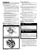
Two- Stage Gas Valve
NOTE: For older model 2- stage furnaces with a Series E gas
valve (see Figure 11), they DO NOT need to have the regulator
springs replaced in the gas valve, but the regulators in the gas
valve must be pre- adjusted for propane applications.
For E valves see Figure 11.
1. Be sure gas and electrical supplies to furnace are off.
2. Remove caps that conceal adjustment screws for high-
and low- heat stage gas valve regulators. See Figure 10.
3. Turn low- heat stage adjusting screw (3/32- in. [2 mm] hex
Allen screw) clockwise (in) 1 full turn. This will increase
the manifold pressure closer to the propane low- heat set
point.
4. Turn high- heat stage adjusting screw (3/32- in. [2 mm]
hex Allen screw) clockwise (in) 2 full turns. This will
increase the manifold pressure closer to the propane
high- heat set point.
5. Do not install regulator seal caps at this time.
For all other gas valves see Figure 11.
1. Be sure main gas and electrical supplies are turned OFF.
2. Remove both regulator seal caps. (See Figure 11)
3. Remove both regulator adjustment screws.
4. Remove both natural gas regulator springs (silver).
5. Install propane gas regulator springs (white).
6. Install regulator adjustment screws.
7. Turn low- heat stage adjusting screw clockwise (inwards)
9.5 turns. This will increase the manifold pressure closer
to the low- heat set point.
8. Turn high- heat stage adjusting screw clockwise (inwards)
13.5 turns. This will increase the manifold pressure closer
to the high- heat set point.
9. Do not install regulator seal caps at this time.
NOTE: For the two- stage furnaces (see Figure 11), they
MUST have both regulator springs replaced and the gas
valve MUST be pre - adjusted.
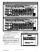
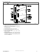
Figure 11
Gas Valve (Two- Stage)
Two - Stage E Valve
A01069
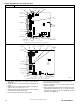
ON
O
F
F
ON/OFF
SWITCH
INLET
PRESSURE
TA P
BURNER ENCLOSURE
REFERENCE PRESSURE TAP
(2-STAGE
AND VARIABLE-SPEED, CONDENSING
FURNACES ONLY)
MANIFOLD
PRESSURE
TA P
LOW-HEAT
ADJUSTMENT
ALLEN SCREW
(UNDER CAP)
HIGH-HEAT
ADJUSTMENT
ALLEN SCREW
(UNDER CAP)
PLUG BUTTON
(2-STAGE AND
VARIABLE–SPEED,
NON–CONDENSING
FURNACES ONLY)
Two- Stage Valve
ON/OFF Switch
Regulator Seal Cap
Regulator Adjustment
Regulator Seal Cap under Cap
1/2” NPT Outlet
1/8” NPT Manifold
Pressure Tap
1/8” NPT Inlet
Pressure Tap
1/2” NPT Inlet
TWO-STAGE
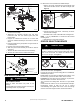
INSTALL MANIFOLD
1. Align the orifices in the manifold assembly with the
support rings on the end of the burner.
2. Insert the orifices in the support rings of the burners.
Manifold mounting tabs should fit flush against the burner
box.
NOTE: If manifold does not fit flush against the burner box, the
burners are not fully seated forward. Remove the manifold and
check burner positioning in the burner box assembly.
3. Attach the green/yellow wire and ground terminal to one
of the manifold mounting screws.
4. Install the remaining manifold mounting screws.
5. Connect the wires to the flame sensor and hot surface
igniter.
6. Connect the wires to both rollout switches.
7. Connect the connector harness to gas valve.
NOTE: Use only propane- resistant pipe dope. Do not use
PTFE thread- seal tape.
8. Insert the gas pipe through the grommet in the casing.
Apply a thin layer of pipe dope to the threads of the pipe
and thread the pipe into the gas valve.
NOTE: Use a back-up wrench on the gas valve to prevent the
valve from rotating on the manifold or damaging the mounting to
the burner box.
9. With a back-up wrench on the inlet boss of the gas valve,
finish tightening the gas pipe to the gas valve.
10. Turn gas on at electric switch on gas valve.
INSTALL LOW GAS PRES SURE
SWITCH
! WARNING
FIRE, EXPLOSION, ELECTRICAL SHOCK
HAZARD
Failure to follow this warning could result in personal injury,
death or property damage.
Gas supply MUST be shut off before disconnecting electrical
power and proceeding with conversion.
! WARNING
ELECTRICAL SHOCK, FIRE OR EXPLOSION HAZARD
Failure to follow this warning could result in personal injury,
death or property damage.
Before installing, modifying, or servicing system, main
electrical disconnect switch must be in the OFF position and
install a lockout tag. There may be more than one disconnect
switch. Lock out and tag switch with a suitable warning label.
Verify proper operation after servicing.
NOTE: Use propane- resistant pipe dope on all connections to
prevent gas leaks. DO NOT use PTFE thread- seal tape.
1. Be sure main gas and electric supplies to furnace are off.
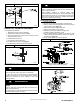
2. Remove 1/8- in. (3 mm) pipe plug from inlet pressure tap
on gas valve. DO NOT DISCARD 1/8-in. (3 mm) PLUG.
3. Apply pipe dope sparingly to the 1/8- in. (3 mm) x 2- in.
(50.8 mm) brass nipple and install the doped end in
1/8- in. (3 mm) tapped opening in gas valve inlet
pressure-tap. Tighten fitting with a small wrench.
4. Apply pipe dope sparingly to the opposite end of the
1/8- in. (3 mm) x 2- in. (50.8 mm) brass coupling. Install
the female end of the female x female x male tee on the
brass coupling.