
Installation Manual
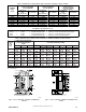

12 440 01 4501 01
Specifications subject to change without notice.
CONDENSATE TRAP
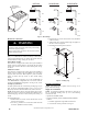
Condensate Trap -- Upflow Orientation
When the furnace is installed in the upflow position, it is not
necessary to relocate the condensate trap or associated tubing.
Refer to Fig. 9 for upflow condensate trap information. Refer to
Condensate Drain section for information how to install the
condensate drain.
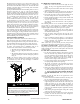
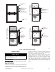
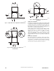
Condensate Trap -- Downflow Orientation.
When the furnace is installed in the downflow position, the
condensate trap will be initially located at the upper left corner of
the collector box, as received from the factory. See the top image
in Fig. 10. When the furnace is installed in the downflow
orientation, the condensate trap must be relocated for proper
condensate drainage. See the bottom image in Fig. 10.
To Relocate the Condensate Trap:
S Ori ent the furnace in the downf low position.
S Fig. 10 shows the conde nsa t e trap a nd tubi ng bef ore and af t er
relocation. Ref er to Fig. 10 to begi n the trap conversi on.
S Refer to Condens ate Drain se ction for inf ormation how to ins tall the
condensa t e drain.
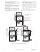
Condensate Trap -- Horizontal Orientation.
Whe n the fur na ce is insta l led in the hori zontal right position, the
condensa t e t r ap wi ll be initially located at the bottom of the collector
box, a s received from the factory. See the top image in Fig. 11.
When the furnace is installed in the horizontal left position, the
condensa t e tr ap wil l be initially located at the top of the collector box,
as received from the factory . See the top image in Fig. 12. In both
case s the trap must be repositioned on t he collector box for prope r
condensate drai nage. See the bottom images in Fig. 11 and 12.
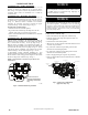
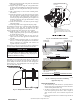
A field--supplied, accessory Horizontal Installation Kit (trap
grom met) is required for all direct--vent hori zontal inst allations (only) .
The kit contains a rubbe r ca s ing grom m e t des i gned t o s eal betwee n
the fur na ce casing a nd the condensate tr ap. Se e Fig. 8.
Remove knockout.
Install grommet before
relocating condensate
trap.
NOTE: Trap grommet is required only for direct-vent
applications.
A11582
Fig. 8 -- Horizontal Drain Trap Grommet
The field--supplied, accessory horizontal drain trap grommet is
ONLY REQUIRED FOR DIRECT VENT APPLICATIONS.
It it NOT required for applications using single-- pipe or
ventilated combustion air venting.
NOTICE
The condensate trap extends below the side of the casing in
the horizontal position. A minimum of 2--in. (51 mm) of
clearance is required between the casing side and the furnace
platform for the trap to extend out of the casing in the
horizontal position. Allow at least 1/4-- in. per foot (20 mm
per meter) of slope down.
NOTICE
To Relocate the Condensate Trap:
S Remove the knockout in the ca sing for the condensate trap.
S Install the grommet in the casing when re quired for dir ect--vent
horizontal appl ications.
S Orient the furnace in the desired position.
S All ow for 2 in. ( 51 mm) of clearance under neat h the fur nace for t he
condensa t e trap a nd drain li ne.
S Fig. 11 shows the condensate trap a nd tubi ng bef ore and af te r
relocation in the hori zontal right posi tion.
S Fig. 12 shows the conde nsa t e trap a nd tubi ng bef ore and af t er
relocation in the hori zontal left posi t ion.
S Refer to the appropria te figure to begi n the trap conversion.
S Refer to Condens ate Drain se ction for inf ormation how to ins tall the
condensa t e drain.
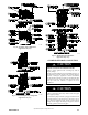
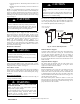
Condensate Trap
Relief Port
Collector Box
Plugs
Pressure Switch
Port
Condensate Trap
Outlet
Condensate Trap
Relief Port
Collector Box
Plug
Vent Elbow
Vent Elbow Clamp
Vent Pipe Clamp
UPFLOW TRAP CONFIGURATION
1 & 2 Stage Units
A11307
Fig. 9 -- Upflow Trap Configuration
(Appearance may vary)