
Specifications
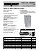


PRODUCT SPECIFICATIONS Gas Furnace: N80ESN, N80ESL
4 441 51 3400 04
Specifications subject to change without notice.
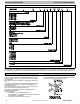
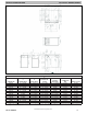
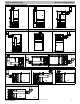
PHYSICAL D
A
T
A
(CONTINUED)
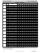
UNIT SIZE
0902116 0902120 0902420 1102120 1102420 1352420 1552420
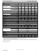
RA TINGS AND PERFORMANCE
Input Btuh*
A
ll Standard
All Low NOx Upflow
88,000 88,000 88,000 110,000 110,000 132,000 154,000
Nonweatherized ICS
A
ll Low Nox
Downflow/Horizontal
84,000 84,000 84,000 105,000 105,000 126,000 147,000
Output Capacity (Btuh)†
A
ll Standard
All Low NOx Upflow
72,000 71,000 72,000 90,000 90,000 107,000 125,000
Nonweatherized ICS
A
ll Low Nox
Downflow/Horizontal
68,000 68,000 69,000 85,000 86,000 102,000 119,000
A
FUE† 80.00 80.00 80.00 80.00 80.00 80.00 80.00
Certified Temperature Rise Range F(C)
35---65
( 1 9 --- 3 6 )
25---55
( 1 4 --- 3 0 )
30---60
( 1 7 --- 3 3 )
30---60
( 1 7 --- 3 3 )
30---60
( 1 7 --- 3 3 )
40---70
( 2 2 --- 3 9 )
45---75
( 2 5 --- 4 1 )
Certified External Static
Pressure
Heat/Cool 0.15/0.50 0.15/0.50 0.15/0.50 0.20/0.50 0.20/0.80 0.20/0.50 0.20/0.50
Airflow CFM‡
Heating 1418 1650 1565 1890 1930 1760 1995
Cooling 1445 1980 1960 2040 2005 1810 1965
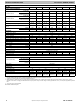
ELECTRICAL
U n i t Vo l t s --- H e r t z --- P h a s e 1 1 5 --- 6 0 --- 1
Operating Voltage Range Min---Max 104---127
Maximum Unit
A
mps 8.3 13 10.3 13.4 10.7 10.7 10.7
Unit
A
mpacity 11 16.90 13.50 17.40 14 14 14
MaximumWireLength(Measure1WayinFt(M)) 33 (10.1) 34 (10.4) 27 (8.2) 33 (10.1) 26 (7.9) 26 (7.9) 26 (7.9)
Minimum Wire Size 14 12 14 12 14 14 14
MaximumFuseorCktBkrSize(Amps)** 15 20 15 20 15 15 15
Transformer (24v) 40va
External Control Heating 12va
Power
A
vailable Cooling 35va
A
ir Conditioning Blower Relay Standard
CONTROLS
Heating Blower Control SolidState Time Operation
Burners (Monoport) 4 4 4 5 5 6 7
Gas Connection Size 1/2in. NPT
GAS CONTROLS
Gas Valve (Redundant)
Mfr. WhiteRodgers
Min. inlet pressure
(In. W.C.)
4.5 (Natural Gas)
Max. inlet pressure
(In. W.C.)
13.6 (Natural Gas)
Ignition Device Hot Surface
Factory installed orifice Size 43
BLOWER DATA
Direct Drive Motor HP 1/2 1 3/4 1 3/4 3/4 3/4
Motor Full Load
A
mps 6.80 11.50 8.80 11.50 8.80 8.80 8.80
RPM (Nominal)Speeds 1050---5 1050---5 1050---5 1050---5 1050---5 1050---5 1050---5
Blower Wheel Diameter x Width --- In. (mm)
10
x
10
(254 x 254)
11
x
11
(279 x 279)
11
x
11
(279 x 279)
11
x
11
(279 x 279)
11 x 11
(279 x 279)
11
x
11
(279 x 279)
11
x
11
(279 x 279)
* Gas input ratings are certified for elevations to 2000 ft. (610 M). In USA, for elevations above 2000 ft. (610 M), reduce ratings 4 percent for each 1000 ft. (305 M) above
sea level. Refer to National Fuel Gas Code NFPA 54/ANSI Z223.1 Table F.4 or furnace installation instructions.
† Capacity in accordance with U.S. Government DOE test procedures.
‡ Airflow shown is for bottom only return-air supply for the as-shipped speed tap. For air delivery above 1800 CFM, see Air Delivery table for other options. A filter is
required for each return-air supply. An airflow reduction of up to 7 percent may occur when using the factory-specified 4-5/16---in. (110 mm) wide, high efficiency media
filter.
** Time---delay type is recommended.
ICS Isolated Combustion System