
Natural Gas to Propane Conversion Instructions

8 AG- KN018SNP- 01
Specifications subject to change without notice.
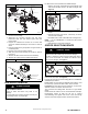
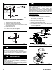
5. Tighten tee finger tight. Use a small open-end wrench for
final tightening. The male end of the tee should be facing
you.
6. Apply pipe dope sparingly to the end of brass tee.
7. Install propane low gas pressure switch on male end of
the female x female x male tee.
8. Tighten switch finger tight.
9. Use a small open-end wrench on base of pressure switch
for final tightening. The contacts of the LGPS should be
pointing toward the inducer motor when complete.
10. The remaining opening on the brass street tee is the new
gas valve inlet pressure tap
11. Install manometer fitting to the open end of the brass
street tee. Or if installation is to be completed later, apply
pipe dope to inlet pressure plug from gas valve install in
open end of brass street tee.
12. Check all fittings for leaks after gas supply has been
turned on.
! WARNING
FIRE AND EXPLOSION HAZARD
Failure to follow this warning could result in personal injury
and/or death.
NEVER test for gas leaks with an open flame. Use a
commercially available soap solution made specifically for the
detection of leaks to check all connections. A fire or explosion
may result causing property damage, personal injury or loss of
life.
! AVERTISSEMENT
RISQUE D’EXPLOSION ET D’INCENDIE
Le fait de ne pas suivre cet avertissement pourrait entraîner
des dommages corporels et / ou la mort.
Ne jamais examiner pour les fuites de gaz avec une flamme
vive. Utilisez plutôt un savon fait specifiquement pour la
détection des fuites de gaz pour verifier tous les connections.
Un incendie ou une explosion peut entrainer des dommages
matériels, des blessures ou la mort.
MODIFY PRESSURE SWITCH WIRING
! CAUTION
UNIT OPERATION HAZARD
Failure to follow this caution may result in unit damage or
improper operation.
Label all wires prior to disconnection when servicing controls.
! PRUDENCE
D’EQUIPEMENT D’OPERATION
Toute erreur de câblage peut être une source de danger et de
panne.
Lors des opérations d’entretien des commandes, étiqueter
tous les fils avant de les déconnecter.
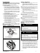
1. Locate the orange wire in the kit with an insulated straight
female spade terminal and an insulated straight male
terminal on the other end.
2. Connect the female terminal to a terminal on the Low Gas
Pressure Switch.
3. Locate the orange wire in the kit with an insulated straight
female spade terminal and an insulated female flag
terminal on the other end.
4. Connect both straight female terminals of the orange
wires to the terminals on the Low Gas Pressure Switch.
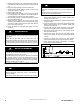
5. Disconnect orange wire from low- heat pressure switch
LPS on inducer housing.
6. Connect the orange wire from the Low Heat Pressure
Switch to the orange wire with the insulated male spade
terminal.
7. Connect the orange wire from the Low Gas Pressure
Switch to the terminal on the Low Heat Pressure Switch.
8. Route orange wires along wire harness. If possible,
secure with wire tie provided in kit.
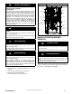
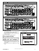
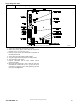
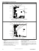
Figure 12
80% Pressure Switch Wiring
A190044