
Natural Gas to Propane Conversion Instructions
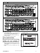

AG- KN018SNP- 01 13
Specifications subject to change without notice.
In Canada, the input rating must be derated by 10 percent for
altitudes of 2000 ft. (610 M) to 4500 ft. (1372 M) above sea
level.
The Conversion Kit Rating Plate accounts for high altitude
derate.
SET GAS INPUT RATE
Sing le- Stage Gas Valve
1. Jumper R and W thermostat connections to call for heat.
(See Figure 13)
2. Check manifold orifices for gas leaks when main burners
ignite.
3. Adjust gas manifold pressure. (Refer to conversion kit
rating plate 344674- 201.
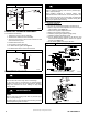
4. Remove cap that conceals gas valve regulator
adjustment screw.
5. Turn adjusting screw counterclockwise (out) to decrease
manifold pressure or clockwise (in) to increase manifold
pressure.
6. Replace gas valve regulator seal cap.
7. Verify manifold pressure is correct.
NOTE: Gas valve regulator seal cap MUST be in place when
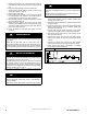
checking input rate. When correct input is obtained, main burner
flame should be clear blue, almost transparent (See Figure 17).
Be sure regulator seal cap is in place when finished.
8. Remove jumper across R and W thermostat connections
to terminate call for heat.
9. Turn furnace gas valve control switch or control knob to
OFF position.
10. Turn off furnace power supply.
11. Remove manometer and on some models remove
pressure tap fitting.
12. Turn furnace gas- valve switch to ON position.
13. Turn on furnace power supply.
14. Set room thermostat to call for heat.
15. Check pressure tap plug for gas leaks when main burners
ignite.
16. Check for correct burner flame.
17. After making the required manifold pressure adjustments,
check and adjust the furnace temperature rise per the
furnace installation instructions.
Fixed- Speed Blower (FCT), Two- Stage Gas Valve
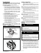
1. Verify SW1 (LHT or TT) on furnace control is turned “ON”.
See Figure 15.
2. Jumper R and W/W1 thermostat connections to call for
heat.
3. Check manifold orifices for gas leaks when main burners
ignite.
4. Adjust gas manifold pressure.
5. Remove caps that conceal adjustment screws for gas
valve regulators. (See Figure 10)
6. Adjust low heat input rate manifold pressure for propane
gas.
7. Turn low heat adjusting screw counterclockwise (out) to
decrease input rate or clockwise (in) to increase input
rate.
8. When correct input is obtained, main burner flame should
be clear blue, almost transparent. (See Figure 17)
9. Jumper R and W/W1 and W2 on control center thermostat
connections. This keeps furnace locked in high heat
operation.
10. Adjust high heat input rate manifold pressure for propane
gas.
11. Turn high heat adjusting screw counterclockwise (out) to
decrease input rate or clockwise (in) to increase input
rate.
12. Replace caps that conceal gas valve regulator adjustment
screws.
13. When correct input is obtained, main burner flame should
be clear blue, almost transparent. (See Figure 17)
14. Remove jumper across R, W1, and W2 after high heat
adjustment to terminate call for heat.
15. Turn setup switch SW1 (TT) on furnace control to OFF
position.
16. Turn furnace gas- valve switch to OFF position.
17. Turn off furnace power supply.
18. Remove manometer from the manifold pressure tap of the
gas valve.
19. Turn on furnace power supply.
20. Set room thermostat to call for heat.
21. Check pressure tap plug for gas leaks when main burners
ignite.
22. Check for correct burner flame.
23. After making the required manifold pressure adjustments,
check and adjust the furnace temperature rise per the
furnace installation instructions.
Variable Speed, Two- Stage Gas Valve
1. Verify SW1-2 on furnace control is turned “ON”. (See
Figure 14)
2. Jumper R and W/W1 thermostat connections to call for
heat.
3. Check manifold orifices for gas leaks when main burners
ignite.
4. Adjust gas manifold pressure. (Refer to conversion kit
rating plate 344674- 201.
5. Remove caps that conceal adjustment screws for gas
valve regulators. (See Figure 11)
6. Adjust low- heat manifold pressure for propane gas. (See
Figure 11)
7. Turn low- heat adjusting screw counterclockwise (out) to
decrease input rate or clockwise (in) to increase input
rate.
NOTE: When correct input is obtained, main burner flame
should be clear blue, almost transparent. (See Figure 17).
8. Jumper R, W/W1 and W2 on control center thermostat
connections. This keeps furnace locked in high- heat
operation.
9. Adjust high- heat manifold pressure for propane gas.
10. Turn high- heat adjusting screw counterclockwise (out) to
decrease input rate or clockwise (in) to increase input
rate.
11. Replace caps that conceal gas valve regulator adjustment
screws.
NOTE: When correct input is obtained, main burner flame
should be clear blue, almost transparent. (See Figure 17).
12. Remove jumper across R, W1, and W2 after high- heat
adjustment to terminate call for heat.
13. Turn setup switch SW1-2 on furnace control to OFF
position.
14. Turn furnace gas valve switch to OFF position.
15. Turn off furnace power supply.
16. Remove manometer and re-install manifold pressure tap
plug.
17. Turn furnace gas valve switch to ON position.
18. Turn on furnace power supply.
19. Set room thermostat to call for heat.
20. Check pressure tap plug for gas leaks when main burners
ignite.
21. Check for correct burner flame.
22. Observe unit operation through two complete heating
cycles.
23. See Sequence of Operation in furnace Installation,
Start- Up, and Operating Instructions.
24. Set room thermostat to desired temperature.
After making the required manifold pressure adjustments, check
and adjust the furnace temperature rise per the furnace
installation instructions.