
Natural Gas to Propane Conversion Instructions


4 AG- KN018SNP- 01
Specifications subject to change without notice.
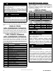
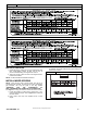
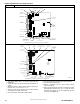
Figure 2 80% Burner
A
ttach Green/Yellow
ground wire here
Manifold Assy
Sensor Flame
Clip, Harness
Burner Assy
Burner Support Assy
Switch, Temp (2)
Ignitor
Bracket Ignitor
A11390
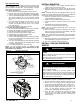
1. Disconnect the gas pipe from gas valve and remove pipe
from the furnace casing.
2. Disconnect the connector harness from gas valve.
Disconnect wires from Hot Surface Igniter (HSI) and
Flame Sensor.
3. Support the manifold and remove the 4 screws that
secure the manifold assembly to the burner box and set
aside.
4. Note the location of the green/yellow wire ground wire for
re-assembly later.
5. Remove wires from both rollout switches.
6. Slide one- piece burner assembly out of slots on sides of
burner box.
7. Remove the flame sensor from the burner assembly.
8. Remove the orifices from the manifold and discard.
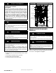
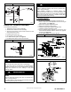
Figure 3
80% Manifold
Gas Valve
Screw (2)
Attach Green/Yellow
ground wire here
Orifice
Manifold
A11395
NOx DEVICE REMOVAL
UNIT DAMAGE HAZARD
Failure to follow this caution may result in unit
damage.
Furnace MUST have low NOx devices removed prior
to operating furnace on propane gas.
CAUTION
!
For NOx device removal, follow these additional steps:
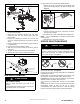
1. Remove the screw underneath the heat exchanger inlet
that secures the NOx device in the heat exchanger. (See
Figure 4)
Figure 4
NOx Device Removal
A02195
2. Use a pair of needle nose pliers to remove the NOx
device.
3. Squeeze the sides of the device, if necessary, to remove
from the heat exchanger.
4. Re-install screw in hole underneath heat exchanger inlet.
NOTE: It is very IMPORTANT to reinstall the NOx bracket
mounting screw.
5. Repeat steps for each heat exchanger.
ORIFICE SELECTION/DERATE
! CAUTION
UNIT DAMAGE HAZARD
Failure to follow this caution may result in unit damage.
DO NOT re- drill burner orifices. Improper drilling may result in
burrs, out- of- round holes, etc. Obtain new orifices if orifice
size must be changed. (See Figure 5)
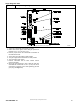
Figure 5 Burner Orifice
BURNER
ORIFICE
BURNER
ORIFICE
A96249
Refer to conversion kit rating plate 344674- 201 to determine
main burner orifice size. (See Figure 6)
Furnace gas input rate on furnace rating plate is for installations
at altitudes up to 2000 ft.
In the U.S.A.; the input rating for altitudes above 2000 ft. must
be reduced by 4 percent for each 1000 ft. above sea level.
In Canada, the input rating must be derated by 10 percent for
altitudes of 2000 ft. to 4500 ft. above sea level.
The Conversion Kit Rating Plate accounts for high altitude
derate.
Install main burner orifices. Do not use PTFE thread- seal tape.
Finger-tighten orifices at least one full turn to prevent
cross-threading, then tighten with wrench. There are enough
orifices in each kit for largest furnace. Discard extra orifices.