
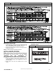
Natural Gas to Propane Conversion Instructions


AG- KN018SNP- 01 3
Specifications subject to change without notice.
!
AVERTISSEMENT
LE FEU, L’EXPLOSION, CHOC ELECTRIQUE,
ET MONOXYDE DE CARBONE
EMPOISONNER
Cette trousse de conversion doit être installée par un servie
d’entretien qualifié, selon les instructions du fabricant et selon
toutes les exigences et tous les codes pertinents de l’autorité
compétente. Assurezvous de bien suivre les instructions dans
cette notice pour réduire au minimum le risque d’incendie,
d’explosion ou la production de monoxyde de carbone
pouvant causer des dommages matériels, de blessure ou la
mort. Le service d’entretien qualifié est responsable de
l’installation de cette trousse. L’installation n’est pas adéquate
ni complète tant que le bon fonctionnement de l’appereil
converti n’a pas été vérfié selon les instructions du fabricant
fornies avec la trousse.
! WARNING
FIRE, EXPLOSION, ELECTRICAL SHOCK
HAZARD
Failure to follow this warning could result in personal injury,
death or property damage.
Gas supply MUST be shut off before disconnecting electrical
power and proceeding with conversion.
! WARNING
FIRE, EXPLOSION, ELECTRICAL SHOCK HAZARD
Failure to follow this warning could result in personal injury,
death or property damage.
Gas supply MUST be shut off before disconnecting electrical
power and proceeding with conversion.
! WARNING
ELECTRICAL SHOCK, FIRE OR EXPLOSION HAZARD
Failure to follow this warning could result in personal injury,
death or property damage.
Before installing, modifying, or servicing system, main
electrical disconnect switch must be in the OFF position and
install a lockout tag. There may be more than one disconnect
switch. Lock out and tag switch with a suitable warning label.
Verify proper operation after servicing.
1. Set room thermostat to lowest setting or “OFF”.
2. Disconnect power at external disconnect, fuse or circuit
breaker.
3. Turn off gas at external shut-off or gas meter.
4. Remove outer doors and set aside.
5. Turn electric switch on gas valve to OFF.
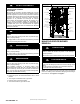
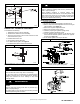
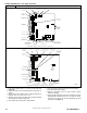
Figure 1
Representative Furnace Drawing
INDUCER MOTOR
ASSEMBLY
PRESSURE
SWITCHES
FLUE COLLECTOR
BOX
GAS VALVE
HOT SURFACE
IGNITOR
BLOWER DOOR
SAFETY SWITCH
FURNACE CONTROL
BOARD
VENT
ELBOW
MAIN LIMIT SWITCH
(BEHIND GAS VALVE)
BLOCKED VENT
SWITCH
FLAME
SENSOR
GAS MANIFOLD
GAS BURNER
BLOWER AND
MOTOR
MANUAL RESET
LIMIT SWITCHES
CAPACITOR/
POWER CHOKE
REPRESENTATIVE DRAWING ONLY, SOME MODELS MAY VARY IN APPEARANCE.
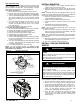
MANIFOLD/ORIFICE/BURNER
REMOVAL
! CAUTION
UNIT OPERATION HAZARD
Failure to follow this caution may result in unit damage or
improper operation.
Label all wires prior to disconnection when servicing controls.
! PRUDENCE
D’EQUIPEMENT D’OPERATION
Toute erreur de câblage peut être une source de danger et de
panne.
Lors des opérations d’entretien des commandes, étiqueter
tous les fils avant de les déconnecter.
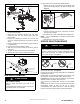
NOTE: Use a back-up wrench on the gas valve to prevent the
valve from rotating on the manifold or damaging the mounting to
the burner box. See Figure 2 and Figure 3.