
Specification Sheet

Specificatio ns subject to change without notice.
518 71 2005 06
33
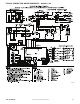
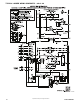
CONTROLS
Operating sequence
When power is supplied to unit, the transformer (TRAN) is
energized.
On units with crankcase heater, heater is also energized.
Cooling — With the thermostat in the cooling position, the
thermostat makes circuit R- O. This energizes the reversing
valve solenoid (RVS) and places the unit in standby condition
for cooling.
As the space temperature rises, the thermostat closes circuit
R- Y. A circuit is made to contactor (C), starting the compressor
(COMP) and outdoor- fan motor (OFM). Circuit R - G is made at
the same time and starts the indoor- fan motor (IFM).
When the thermostat is satisfied, contacts open, deenergizing
C. The COMP and OFM stop, and the IFM stops after the
preselected time delay.
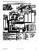
Heating — On a call for heat, thermostat makes circuits R- Y
and R - G.
A circuit is made to C, starting COMP and OFM. Circuit R - G
also is completed, energizing IFR and starting IFM after the
selected time delay.
Should room temperature continue to fall, circuit R- W is made
through second - stage thermostat. If optional electric heat
package is used, a relay is energized, bringing on first bank of
supplemental electric heat. When thermostat is satisfied,
contacts open, deenergizing contactor and relay; motors and
heaters deenergize.
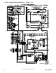
Defrost — Defrost board (DB) is a time and temperature
control, which includes a field- selectable time period (dip
switch 1 and 2 on the board) between checks for defrost (30,
60, 90, or 120 minutes). Electronic timer and defrost cycle start
only when contactor is energized and defrost thermostat (DFT)
is closed.
Defrost mode is identical to cooling mode, except outdoor fan
motor s tops and a bank of optional electric heat turns on to
warm air supplying the conditioned space.
NOTE:
1. Compressor time delay occurs through the defrost
control board.
2. Defrost control board has built in 5 minute compressor
delay; once the compressor has started and then
stopped, it cannot be restarted again until 5 minutes
have elapsed.
GUIDE SPECIFICATIONS
Packaged Heat Pump System
HVAC Guide Specifications
Size Range: 2 to 5 Tons, Nominal Cooling
Part 1General
SYSTEM DESCRIPTION
Outdoor, packaged, air- to - air heat pump unit utilizing a
hermetic scroll compressor for cooling duty and optional
electric heating. Unit shall discharge supply air vertically or
horizontally as shown on contract drawings. Outdoor fan/coil
section shall have a draw- thru design with vertical discharge
for minimum sound levels.
QUALITY ASSURANCE
A. Unit shall be rated in accordance with AHRI Standards
210/240 and 270.
B. Unit shall be designed in accordance with UL Standard
1995.
C. Unit shall be manufactured in a facility registered to ISO
9001 manufacturing quality standard.
D. Unit shall be UL listed and c- UL certified as a total
package for safety requirements.
E. Roof curb shall be designed to conform to NRCA
Standards.
F. Insulation and adhesives shall meet NFPA 90A
requirements for flame spread and smoke generation.
G. Cabinet insulation shall meet ASHRAE Standard 62P.
DELIVERY, STORAGE AND HANDLING
Unit shall be s tored and handled per manufacturer ’s
recommendations.
Part 2 Products
EQUIPMENT
A. General:
Factory- assembled, single- piece, heat pump unit.
Contained within the enclosure shall be all factory wiring,
piping, controls, refrigerant charge (R- 410A), and special
features required prior to field start- up.
B. Unit Cabinet:
1. Unit cabinet shall be constructed of phosphated,
zinc- coated, pre- painted steel capable of withstanding
500 hours of salt spray.
2. Normal service shall be through 3 removable cabinet
panels.
3. The unit shall be constructed on a rust proof unit base
that has an externally trapped, integrated sloped drain.
4. Indoor fan compartment top surface shall be insulated
with a minimum 1/2- in. (13 mm) thick, flexible fiberglass
insulation, coated on the air side and retained by
adhesive and mechanical means. The indoor wall
sections will be insulated with a minimum semi- rigid,
foil- faced board capable of being wiped clean.
Aluminum foil- faced fiberglass insulation shall be used
in the entire indoor air cavity section.
5. Unit shall have a field- supplied condensate trap.
6. Metal Insulated Duct Covers for side discharge will be
standard on all sizes.
7. Unit insulation conforms to ASHRAE 62P.
C. Fans:
1. The indoor fan s hall be 5- speed, direct- drive, as shown
on equipment drawings.
2. Fan wheel shall be made from steel and shall be
double- inlet type with forward - curved blades with
corrosion resistant finish. Fan wheel shall be
dynamically balanced.
3. Outdoor fan shall be direct- drive, propeller - type with
aluminum blades riveted to corrosion resistant steel
spiders, be dynamically balanced, and discharge air
vertically.
D. Compressor:
1. Fully hermetic compressors with factory - installed
vibration isolation.
2. Scroll compressors shall be standard on all units.
E. Coils:
Indoor and outdoor coils shall have aluminum plate fins
mechanically bonded to seamless copper tubes with all joints
brazed. Tube sheet openings shall be belled to prevent tube
wear.
F. Refrigerant Metering Device:
Refrigerant metering device shall be thermostatic expan-
sion valve or fixed orifice for cooling, and fixed orifice for
heating.