
Specification Sheet


Specificatio ns subject to change without notice.
518 71 2005 06
23
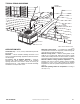
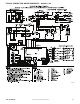
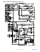
TYPICAL PIPING AND WIRING
INDOOR
THERMOSTAT
DISCONNECT
PER NEC*
FROM
POWER
SOURCE
RETURN
AIR
TOP COVER
POWER ENTRY
CONTROL ENTRY
*NEC - National Electrical Code
A09240
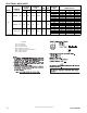
APPLICATION DATA
Condensate trap — A 2- in. (51 mm) condensate trap must be
field supplied.
Ductwork — Secure downflow discharge ductwork to roof
curb. For horizontal discharge applications, attach ductwork to
unit with flanges.
To convert a unit to downflow discharge — Units are
equipped with factory- installed inserts in the downflow
openings. Removal of the inserts is similar to removing an
electrical knock - out. Units installed in horizontal discharge
orientation do not require duct covers.
Maximum cooling airflow — To minimize the possibility of
condensate blow- off from the evaporator, airflow through the
units should not exceed 450 CFM per ton.
Minimum c ooling airflow — Minimum cooling airflow is 350
CFM per ton in cooling mode. Airflow can be lower in certain
modes when humidity removal is an issue however, low airflow
could result in indoor coil freezing and/or refrigerant floodback.
Minimum ambient cooling operation temperature —All
standard units have a minimum ambient cooling operating
temperature of 40_F(4.4_C). With accessory low ambient
temperature kit, units can operate at temperatures down to 0_F
(17.8_C).
Maximum operating outdoor air temperature for cooling is
125_F (51.7_C).