
Installation Manual

22 51801200404
Specifications are subject to change without notice.
HIGH LOW COM
QC5
QC4
QC3
KZ
KL
07 09 080L0
ALO
R13 C8 R11 Q1
Q3
D2
AL2
DCR QCR
QC1
C
RL
01
G1
G2
Z1
A7 R9 AB A15
C4
C9
C0
QIL Z2 06 04
U1
C3
R4 RL4
JWZ
C7
D5 D3
R3 R5 R6
R2
JW5
QCB
Y
R W2 Y C W3W3W2 W2C
JW4
P2
JW3
P4
P1
W2W3
Y2 Y1
YDH
GCR
SSTZ-8
P3
SDL
24VAC/R3AMP CDM/C
F1
STD
DEHUM
A09059
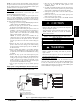
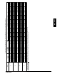
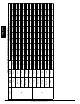
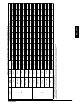
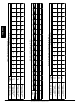
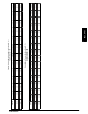
Fig. 18 -- Interface Fan Board (IFB)
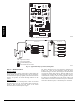
COMPRESSOR
ACCUMULATOR
OUTDOOR COIL
INDOOR COIL
LCS
LEGEND
HPS – High Pressure Switch
LCS – Loss of Charge Switch
Accurater
®
Metering De vice
Arrow indicates direction of flo w
Position
HP S
TXV in Bypass
Metering
Position
C03012
Fig. 19 -- Typical Heat Pump Operation, Heating Mode
Step 3 — Defrost Control
Defrost Control
The defrost control is used in all R--410A heat pump models. Its
features include selectable defrost intervals of 30, 60, 90 minutes,
and standard defrost speed up capability. This section describes the
sequence of operation and trouble shooting methods for this
control.
Defrost
Sequence
The defrost control is a time/temperature control that has field
selectable settings of 30, 60, and 90 minutes. These represent the
amount of time that must pass after closure of the defrost
thermostat before the defrost sequence begins.
The defrost thermostat senses coil temperature throughout the
heating cycle. When the coil temperature reaches the defrost
thermostat setting, it will close, which energizes the DFT terminal
and begins the defrost timing sequence. When the DTF has been
energized for the selected time, the defrost cycle begins, and the
control shifts the reversing valve into cooling position, and turns
the outdoor fan off. This shifts hot gas flow into the outdoor coil
which melts the frost from the coil. The defrost cycle is terminated
when defrost thermostat opens, or automatically after 10 minutes.
PHD4, WPH4