
Installation Manual

12 51801200404
Specifications are subject to change without notice.
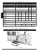
Table 1 – Physical Data
24 30 36 42 48 60
Unit Size 2 2.5 3 3.5 4 5
Shipping Weight (lb)
(kg)
365
166
395
179
440
200
475
215
500
227
515
234
Compressor Quantity 1
Ty pe Scroll
Refrigerant R-410A
Refrigerant Quantity (lb)
Quantity (kg)
7.5
3.4
9.0
4.1
8.9
4.0
11.2
5.1
9.9
4.5
11.9
5.4
Refrigerant Metering Device Indoor TXV, Outdoor Dual Accuraters
Indoor Ac-
curater,
Outdoor
Dual Ac-
curaters
Indoor TX V, Out-
door Dual Ac-
curaters
Orifice ID (in)
(mm)
N/A
0.080 (1)
2.03 (1)
N/A
Orifice OD (in)
(mm)
0.032 ( 2)
0.81 ( 2)
0.035 ( 2)
0.89 ( 2)
0.040 ( 2)
1.02 ( 2)
0.046 ( 2)
1.17 ( 2)
0.046 ( 2)
1.17 ( 2)
0.052 ( 2)
1.32 ( 2)
Outdoor Coil
Rows...Fins/in,
face area (sq. ft.)
1...21
15.4
1...21
18.8
1...21
17.5
1...21
23.3
1...21
23.3
2...21
17.5
Outdoor Fan
Nominal Airflow (cfm)
Diameter (in.)
Diameter (mm)
Motor hp (rpm)
2500
24
610
1/12 (810)
3000
24
610
1/10 (810)
3600
26
660
1/5 (810)
4000
26
660
1/5 (810)
4000
26
660
1/5 (810)
3800
26
660
1/4 (810)
Indoor Coil
Rows...Fins/in,
face area (sq. ft.)
3...17
3.7
3...17
3.7
2...15
5.6
3...17
4.7
3...17
4.7
3...17
5.6
Indoor Blower
Nominal Airflow (cfm)
Size (in.)
Size (mm)
Motor hp (rpm)
800
10 x 10
254 x 254
1/2
1000
10 x 10
254 x 254
1/2
1200
11 x 10
279 x 254
1/2
1350
11 x 10
279 x 254
1/2
1600
11 x 10
279 x 254
1
1750
11 x 10
279 x 254
1
High Pressure Switch (psig)
Cutout
Reset (Auto)
650 +/- 15
420 +/- 25
Loss-of-Charge/Low Pressure Switch (psig)
Cutout
Reset (Auto)
20 +/- 5
45 +/- 10
Return Air Filters
disposable
2 ea ch 20x12x1 in.
508x305x25 mm
1 ea ch 24x16x1 in.
610x406x25 mm
24x18x1 in.
610x457x25 mm
1 ea ch 24x14x1 in.
610x356x25 mm
24x16x1 in.
610x406x25 mm
1 ea ch 24x16x1 in.
610x406x25 mm
24x18x1 in.
610x457x25 mm
*Required filter sizes shown are based on the larger of the AHRI (Air Conditioning Heating and Refrigeration Institute) rated cooling airflow or the heating airflow
velocity of 300---350 ft/minute for throwaway type or 450 ft/minute for high ---capacity type. Air filter pressure drop for non ---standard filters mu st not exceed 0.08
IN. W.C.
{ If using accessory filter rack refer to the filter rack installation instructions for correct filter size and quantity.
Table 2 – Minimum Airflow for Reliable Electric Heater Operation (CFM)
SIZE 24 30 36 42 48 60
AIRFLOW (CFM) 800 1025 1250 1400 1710 1800
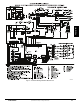
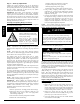
INDOOR
THERMOSTAT
DISCONNECT
PER NEC
FROM
POWER
SOURCE
RETURN
AIR
TOP COVER
POWER ENTRY
CONTROL ENTRY
A09098
Fig. 13 -- Typical Installation
PHD4, WPH4