
Owners Manual


PRODUCT SPECIFICATIONS Split System Heat Pump: NXH6
4 428 51 6203 00
Specifications subject to change wi thout notice.
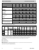
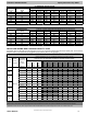
PHYSICAL DATA
Model Size 18 24 30 36 42 48 60
Nominal Cooling Capacit y (BTU/ hr ) 18,000 24,000 30,000 36,000 42,000 48,000 60,000
Nominal SEER 16.0 16.0 16.0 16.0 16.0 16.0 16.0
Compressor Type Scroll
REFRIGERANT (R- 410A)
Control TXV (R- 410A Hard Shutoff)
Charge (lb) 7.0 7.6 9.75 11.2 9.92 9.87 13.0
COND FAN Propeller Type, Direct Drive
Air Discharge Vertical
Air Qty (CFM) 2233 3223 3223 3223 3770 4046 4400
Motor HP 1/12 1/12 1/12 1/12 1/3 1/4 1/3
Motor RPM 810 810 810 810 700 810 767
COND COIL
Face Area (Sq ft) 19.30 20.10 20.10 20.10 20.10 20.10 35.47
Fins per In. 20 20 20 20 20 20 20
Rows 1 1 2 2 2 2 2
Circuits 5 5 6 8 8 8 12
VALVE CONNECT. (In. ID)
Vapor 5/8 3/4 7/8 7/8
Liquid 3/8
REFRIGERANT TUBES* (In. OD)
Vapor (0- 80 Ft Tube Length) 5/8 3/4 7/8 11/8
Liquid (0- 80 Ft Tube Length) 3/8
*Units are rated with 25 ft (7.6 m) of lineset length. See Vapor Line Sizing and Cooling Capacity Loss table when using other sizes and lengths of lineset.
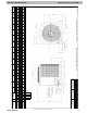
Note: See unit Installation Instruction for proper installation.
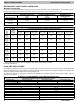
ELECTRICAL DATA (208/230- 1- 60, voltage range 197V - 253V)
UNIT
SIZE
V
/
PH
OPER VOLT S* COMPR FAN
MCA
MIN
WIRE
SIZE †
MIN
WIRE
SIZE †
MAX
LENGTH
FT (M) ††
MAX
LENGTH
FT (M) ††
MAX
FUSE** or
CKT BRK
A
MPS
MAX MIN LRA RLA FLA 60 C 75 C 60 C 75 C
18
208/230/1 253 197
56.3 10.5 0.5 13.6
14
14 58 (18) 55 (17) 20
24
62.9 11.9 0.6 15.5
14
14 51 (15) 48 (15) 25
30 72.5 15.4 0.6 19.9 14 14 40 (12) 38 (11) 30
36 75.0 16.8 0.6 21.6 12 12 58 (18) 55 (17) 35
42 123.9 20.0 2.8 27.8 10 10 72 (22) 68 (21) 40
48 130.0 24.4 1.3 31.8 8 10 98 (30) 60 (18) 45
60 152.5 24.9 2.8 33.9
8
10 92 (28) 56 (17) 50
* Permissible limits of the voltage range at which the unit will operate satisfactorily
{ If wire is applied at ambient greater than 30_C, consult table 310- 16 of the NEC (NFP A 70). The ampacity of non- metallic- sheathed cable (NM), trade
name ROMEX, shall be that of 60_C conditions, per the NEC (NFPA 70) Article 336- 26. If other than uncoated (no- plated), 60 or 75_C insulation, copper wire
(solid wire for 10 AWG or smaller, stranded wire for larger than 10 AWG) is used, consult applicable tables of the NEC (NFPA 70).
} Length shown is as measured 1 way along wire path between unit and service panel for voltage drop not to exceed 2%.
** Time- Delay fuse.
FLA - Full Load Amps
LRA - Locked Rotor Amps
MCA - Minimum Circuit Amps
RLA - Rated Load Amps
NOTE: Control circuit is 24- V on all units and requires external power source. Copper wire must be used from service disconnect to unit.
All motors/compressors contain internal overload protection.
Complies with 2010 requirements of ASHRAE Standards 90.1