
Installation Manual
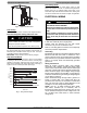

INST ALLATION INSTRUCTIONS R- 410A Split System Heat Pumps
428 01 5110 00 5
Specifications subject to change without notic e.
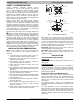
Fig. 4 - Liquid Line Filter Drier
Leak Testing
Leak test all joints; indoors, outdoors, and refrigerant tubing.
Evacuate Refrigerant Tubing and Indoor Coil
CAUTION
!
UNIT DAMAGE HAZARD
Failure to follow this caution may result in equipment
damage or improper operation.
Never use the system compressor as a vacuum pump.
Refrigerant tubes and indoor coil should be evacuated using
the recommended deep vacuum method of 500 microns. An
alternate triple evacuation method may be used. See triple
evacuation method in Service Manual.
IMPORTANT: Always break a vacuum with dry nitrogen.
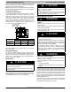
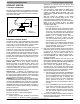
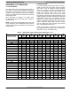
Deep Vacuum Method
The deep vacuum method requires a vacuum pump capable
of pu llin g a va c u u m o f 50 0 mic ron s an d a va c u u m gage
capable of accurately measuring this vacuum depth. The
deep vacuum method is the most positive way of assuring a
system is free of air and liquid water. (See Fig.5)
500
MINUTES
01234567
1000
1500
LEAK IN
SYSTEM
VACUUM TIGH
T
TOO WET
TIGHT
DRY SYSTEM
2000
MICRONS
2500
3000
3500
4000
4500
5000
Fig. 5 - Deep Vacuum Graph
Final Tubing Check
IMPORTANT: Check to be certain factory tubing on both
indoor and outdoor unit has not shifted during shipment.
Ensure tubes are not rubbing against each other or any
sheet metal. Pay close attention to feeder tubes, making sure
wire ties on feeder tubes are secure and tight, as applicable.
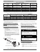
ELECTRICAL WIRING
!
WARNING
ELECTRICAL SHOCK HAZARD
Failure to turn off the main (remote) electrical dis-
connect device could result in personal injury or
death.
Before installing, modifying or servicing system,
turn OFF the main (remote) electrical disconnect
device. There may be more than one disconnect
device.
Supply voltage must be 208/230 volts (197 volt minimum
to 253 volts maximum) 60 Hz single phase.
Outdoor units are approved for use with copper
conductors only. Do not use aluminum wire.
Refer to unit rating plate for minimum circuit ampacity
and circuit protection requirements.
Grounding
Permanently ground unit in accordance with the National
Electrical Code and local codes or ordinances. Use a
copper conductor of the correct size from the grounding
lug in control box to a grounded connection in the service
panel or a properly driven and electrically grounded
ground rod.
Wiring Connections
Make all outdoor electrical supply (Line Voltage)
connections with raintight conduit and fittings. Most
codes require a disconnect switch outdoors within sight
of the unit. Consult local codes for special requirements.
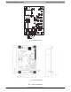
Route electrical supply (Line Voltage) wiring through
knockout hole in bottom of Control Box. Connect wires to
Contactor and Ground Lug according to Wiring Diagram
on unit. Refer to Figure 6.
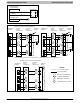
Route thermostat wiring through rubber grommet in
bottom of Control Box. Low voltage lead wires are
provided in the control box for connection to thermostat
wires (use wire nuts). Refer to Wiring Diagram on unit
and Figure 7 for low voltage wiring examples.
NOTE: Use No. 18 AWG (American Wire Gage)
color- coded, insulated (35 ° C minimum) wire. If
thermostat is located more than 100 feet (30.5 m) from
unit as measured along the control voltage wires, use
No. 16 AWG color- coded wires to avoid excessive
voltage drop.