
Installation Manual
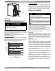


INST ALLATION INSTRUCTIONS R- 410A Split System Heat Pumps
4 428 01 5110 00
Specifications subject to change without notic e.
Table 1 - Accessory Usage
Accessory
REQUIRED FOR LOW–AMBIENT
COOLING APPLICATIONS
(Below 55F / 12.8C)
REQUIRED FOR
LONG LINE APPLICATIONS*
REQUIRED FOR
SEA COAST APPLICATIONS
(Within 2 miles / 3.22 km)
Accumulator Standard Standard Standard
Compressor Start Assist Capacitor and
Relay
Ye s Ye s No
Crankcase Heater Ye s
Ye s
No
Evaporator Freeze Thermostat Ye s No No
Isolation Relay Yes No No
Liquid Line Solenoid Valve No See Long–Line Application Guideline No
Low Ambient Switch Ye s } No No
Support Fee t Recommended No Recommended
* For tubing line sets between 80 and 200 ft. (24.38 and 60.96 m) an d/or 20 ft. (6.09 m) vertical differential, refer to Residential Piping and Lon gline Guideline.
} In units equipped with ECM OD motor, motor needs to be replaced per u nit accessor y guide to work properly. This motor kit comes with a new defrost board
that also needs to be installed. Unit will not meet AHRI rated efficiency once motor and defrost board are replaced to use this accessory.
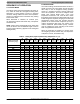
Table 2 - Refrigerant Connections and Recommended Liquid and Vapor Tube Diameters (In.)
UNIT SIZE
LIQUID
RATED VAPOR
up to 80 ft. (24.38 m)*
Connection Diameter Tube Diameter Connection Diameter Rated Tube Diameter
18, 24 3/8 3/8 5/8 5/8
30, 36 3/8 3/8 3/4 3/4
42, 48 3/8 3/8 7/8 7/8
60 3/8 3/8 7/8 1- 1/8
* Units are rated with 25 ft. (7.6 m) of lineset. See Specification sheet for performance data when using different size and length linesets.
Notes:
1. Do not apply capillary tube or fixed orifice indoor coils to these units.
2. For Tubing Set lengths between 80 and 200 ft. (24.38 and 60.96 m) horizontal or 35 ft. (10.7 m) vertical differential 250 ft. (76.2 m) Total Equi valent Length),
refer to the Long Line Applications Guideline.
Outdoor Unit Connected to Factory Approved
Indoor Unit
These outdoor units are c arefully evaluated and listed with
specific indoor coils for proper system performance.
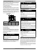
Install Adapter T ube (36, 42, and 60 Units Only)
1. Remove plastic retainer holding outdoor piston in liquid
service valve.
2. Check outdoor piston size with matching number listed
on unit rating plate.
3. Locate plastic bag taped to unit containing adapter
tube.
4. Remove Teflon seal from bag and install on open
end of liquid service valve. (See Fig. 3.)
5. Remove adapter tube from bag and connect threaded
nut to liquid service valve. Tighten nut finger- tight and
then with wrench an additional 1/2 turn (15 ft- lb). DO
NOT OVER TIGHTEN!
PISTON BODY
LIQUID SERVICE VALVE
PISTON
PLASTIC WASHER
ADAPTER TUBE
BRASS NUT
Fig. 3 - Liquid Service Valve
NOTE: 18, 24, 30, and 48 units have an OD TXV installed
for heating expansion and do not require a piston. These
units have a standard AC liquid service valve.
Refrigerant Tubing and Sweat Connections
Connect vapor tube to fitting on outdoor unit vapor service
valves (see Table 2.) Connect liquid tubing to adapter tube
on liquid service valve (36, 42, 60) or to liquid service valve
(18, 24, 30, 48). Use refrigerant grade tubing.
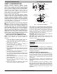
CAUTION
!
UNIT DAMAGE HAZARD
Failure to follow this caution may result in equipment
damage or improper operation.
Service valves must be wrapped in a heat- sinking
material such as a wet cloth while brazing.
CAUTION
!
UNIT DAMAGE HAZARD
Failure to follow this caution may result in equipment
damage or improper operation.
Installation of filter drier in liquid line is required.
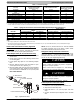
Install Liquid Line Filter Drier Indoor
Refer to Fig. 4 and install filter drier as follows:
1. Braze 5 in. (127 mm) liquid tube to the indoor coil.
2. Wrap filter drier with damp cloth.
3. Braze filter drier to 5 in. (127 mm) liquid tube from
step 1.
4. Connect and braze liquid refrigerant tube to the filter
drier.