
Specifications

PRODUCT SPECIFICATIONS Fan Coils: FCM4X
8 496 51 4202 02
Specifications are subject to change without notice.
NOTES:
1. Contact manufacturer for cooling capacities at conditions other
than shown in table.
2. Formulas:
Leaving db = entering db - sensible heat cap.
1.09 x CFM
Leaving wb = wb corresponding to enthalpy of air leaving coil
(h
lwb
)
h
lwb
=h
ewb
- total capacity (Btuh)
4.5 x CFM
where h
ewb
= enthalpy of air entering coil. Direct interpolation is
permissible. Do not extrapolate.
3. SHC is based on 80_F db temperature of air entering coil.
Below 80_F db, subtract (Correction Factor x CFM) from SHC.
Above 80_F db, add (Correction Factor x CFM) to SHC.
4. Bypass Factor = 0 indicates no psychometric solution. Use
bypass factor of next lower EWB for approximation.
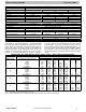
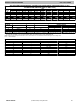
SHC CORRECTION FACT OR
BYPASS
FACTOR
ENTERING AIR DRY- BULB TEMPERATURE (_F)
79 78 77 76 75 Under 75
81 82 83 84 85 Over 85
Correction Factor
0.10 .098 1.96 2.94 3.92 4.91
Use formula
shown
below
0.20 0.87 1.74 2.62 3.49 4.36
0.30 0.76 1.53 2.29 3.05 3.82
Interpolation is permissible.
Correction Factor = 1.09 x (1 - BF) x (db - 80)
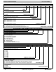
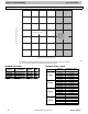
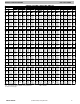
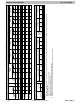
ESTIMATED SOUND POWER LEVEL (dBA)
MODEL
CONDITIONS OCTAVE BAND CENTER FREQUENCY
CFM ESP 63 125 250 500 1000 2000 4000
FCM4X24
400 0.25 61.0 57.0 55.0 50.0 48.0 46.0 42.0
600 0.25 62.7 58.7 56.7 51.7 49.7 47.7 43.7
800 0.25 64.0 60.0 58.0 53.0 51.0 49.0 45.0
1000 0.25 65.0 61.0 57.0 56.0 52.0 50.0 46.0
1200 0.25 65.8 61.8 57.8 56.8 52.8 50.8 46.8
1400 0.25 66.4 62.4 58.4 57.4 53.4 51.4 47.4
FCM4X36
400 0.25 61.0 57.0 55.0 50.0 48.0 46.0 42.0
600 0.25 62.7 58.7 56.7 51.7 49.7 47.7 43.7
800 0.25 64.0 60.0 58.0 53.0 51.0 49.0 45.0
1000 0.25 65.0 61.0 59.0 54.0 52.0 50.0 46.0
1200 0.25 65.8 61.8 59.8 54.8 52.8 50.8 46.8
1400 0.25 66.4 62.4 58.4 57.4 53.4 51.4 47.4
1600 0.25 67.0 63.0 59.0 58.0 54.0 52.0 48.0
FCM4X48
400 0.25 61.0 57.0 55.0 50.0 48.0 46.0 42.0
600 0.25 62.7 58.7 56.7 51.7 49.7 47.7 43.7
800 0.25 64.0 60.0 58.0 53.0 51.0 49.0 45.0
1000 0.25 65.0 61.0 59.0 54.0 52.0 50.0 46.0
1200 0.25 65.8 61.8 59.8 54.8 52.8 50.8 46.8
1400 0.25 66.4 62.4 58.4 57.4 53.4 51.4 47.4
1600 0.25 67.0 63.0 59.0 58.0 54.0 52.0 48.0
FCM4X60
600 0.25 62.7 58.7 56.7 51.7 49.7 47.7 43.7
800 0.25 64.0 60.0 58.0 53.0 51.0 49.0 45.0
1000 0.25 65.0 61.0 59.0 54.0 52.0 50.0 46.0
1200 0.25 65.8 61.8 59.8 54.8 52.8 50.8 46.8
1400 0.25 66.4 62.4 60.4 55.4 53.4 51.4 47.4
1600 0.25 67.0 63.0 61.0 56.0 54.0 52.0 48.0
1800 0.25 67.5 63.5 59.5 58.5 54.5 52.5 48.5
2000 0.25 68.0 64.0 60.0 59.0 55.0 53.0 49.0
2150 0.25 68.3 64.3 60.3 59.3 55.3 53.3 49.3
*Est. sound power levels have been derived using the method described in the 1987 ASHRAE HVAC Systems & Applications Handbook, chapter 52, p.
52.7.
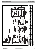
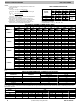
AIRFLOW PERFORMANCE CORRECTION FACTORS
HEATER KW ELEMENTS
STATIC PRESSURE CORRECTION (in wc)
Sizes 24- 48 Size 60
0 0 +.02 +.03
5 1 +.01 +.02
8, 10 2 0 0
9, 15 3 –.02 –.03
20 4 –.04 –.06
18, 24, 30 6 –.06 –.10
The FCM4X airflow performance table was developed using fan coils with 10kW electric heaters (2 elements) in the units. For fan coils with heaters made
up of a different number of elements, the external available static at a given CFM from the table may be corrected by adding or subtracting pressure. Use
table for this correction.
FACTORY- INSTALLED FILTER STATIC PRESSURE DROP (in wc)
MODEL CFM
FCM4X 400 600 800 1000 1200 1400 1600 1800 2000
24 0.020 0.044 0.048 0.072 0.100 — — — —
36 — 0.020 0.035 0.051 0.070 0.092 — — —
48 — — 0.035 0.051 0.070 0.092 0.120 — —
60 — — — 0.038 0.053 0.070 0.086 0.105 0.133