
Installation Manual

INST ALLATION INSTRUCTIONS Fan Coils: FCM4X
496 01 4201 04 9
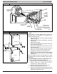
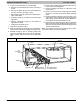
Procedure 5. — Refrigerant Tubing Connection and
Evacuation
Use accessory tubing package or field- supplied tubing of
refrigerant grade. Insulate entire suction tube if
field- supplied tubing is used. Tubing package has an
insulated suction tube. Do not use damaged, dirty, or
contaminated tubing because it may plug refrigerant flow
control device. Always evacuate coil and field- supplied
tubing to 500 microns before opening outdoor unit service
valves.
!
CAUTION
PRODUCT DAMAGE HAZARD
Failure to follow this caution may result in product or
property damage.
A brazing shield MUST be used when tubing sets are
being brazed to the unit connections to prevent dam-
age to the unit surface and condensate pan fitting
caps.
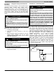
Units have sweat suction and liquid tube connections.
Make suction tube connection first.
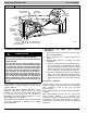
1. Cut tubing to correct length.
2. Insert tube into sweat connection on unit until it
bottoms.
3. Braze connection using silver bearing or non- silver
bearing brazing materials. Do not use solder
(materials which melt below 800F / 427C). Consult
local code requirements.
!
CAUTION
PRODUCT DAMAGE HAZARD
Failure to follow this caution may result in product or
property damage.
Wrap a wet cloth around rear of fitting to prevent dam-
age to TXV and factory made joints.
4. Evacuate coil and tubing system to 500 microns using
deep vacuum method.
Procedure 6. — Condensate Drain
!
CAUTION
PRODUCT DAMAGE HAZARD
Failure to follow this caution may result in product or
property damage.
The conversion of the fan coil to downflow requires
special procedures for the condensate drains on both
A- coil and Slope- units. The vertical drains have an
overflow hole between the primary and secondary
drain holes. This hole is plugged for all applications
except downflow, but must be used for downflow.
During the conversion process, remove the plastic
cap covering the vertical drains only and discard. Re-
move the plug from the overflow hole and discard. At
completion of the downflow installation, caulk
around the vertical pan fitting to door joint to retain
the low air leak performance of the unit.
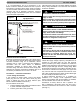
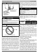
To connect drains, the cap openings must be removed.
Use a knife to start opening near tab and using pliers, pull
tab to remove disk. Clean edge of opening if necessary
and install the condensate line. Finally, caulk around lines
where they exit fitting to retain low leak rating of the unit.
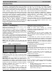
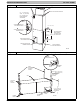
Units are equipped with primary and secondary 3/4- in.
FPT drain connections. For proper condensate line
installation see Figures 1, 2, 3, 5, and 6. To prevent
property damage and achieve optimum drainage
performance, BOTH primary and secondary drain lines
should be installed and include properly sized condensate
traps. (See Figures 11 and 12.) Factory- approved
condensate traps are available. Be sure to install plastic
push- in plugs in unused condensate drain fittings. It is
recommended that PVC fittings be used on plastic
condensate pan. Do not over- tighten. Finger- tighten plus
1- 1/2 turns. Use pipe dope.
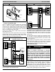
Figure 11
Recommended Condensate Trap
2” MIN
(51 mm)
UNIT
2” MIN
(51 mm)