
Installation Manual

INST ALLATION INSTRUCTIONS Fan Coils: FCM4X
496 01 4201 04 7
It is a recommendation, but not a requirement, to use
flexible connectors between ductwork and unit to prevent
transmission of vibration. When electric heater is installed,
use heat resistant material for flexible connector between
ductwork and unit at discharge connection. Ductwork
passing through unconditioned space must be insulated
and covered with vapor barrier.
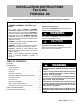
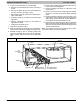
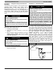
Figure 7
Mobile Home or Manufactured Hous-
ing Applications
UNIT AGAINST WALL
1/8” (3.18 mm) THICK ANGLE
MOUNTING BRACKET
(TYPICAL BOTH SIDES)
SECURE FAN COIL TO STRUCTURE
UNIT AWAY FROM WALL
PIPE STRAP
(TYPICAL BOTH SIDES)
OR
SECURE UNIT TO FLOOR
ANGLE BRACKET OR PIPE STRAP
4” (101.6 mm) MAX
()
4” 101.6 mm MAX
A07141
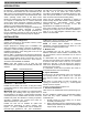
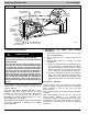
DOWNFLOW
BASE KIT (EBAC**NCB)
Ductwork Acoustical T reatment
Metal duct systems that do not have a 90 elbow and 10
ft. of main duct to first branch takeoff may require internal
acoustical insulation lining. As an alternative, fibrous
ductwork may be used if constructed and installed in
accordance with the latest edition of SMACNA
construction standard on fibrous glass ducts. Both
acoustical lining and fibrous ductwork shall comply with
National Fire Protection Association Standards 90A or B
as tested by UL Standard 181 for Class 1 air ducts.
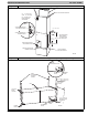
Procedure 4. — Electrical Connections
A. Line- Voltage Connections
If unit contains an electric heater , remove and discard
power plug from fan coil and connect male plug from
heater to female plug from unit wiring harness. (See
Electric Heater Installation Instructions.)
For units without electric heat:
1. Connect 208/230v power leads from field disconnect
to yellow and black stripped leads.
2. Connect ground wire to unit ground lug.
Check all factory wiring per unit wiring diagram and inspect
factory wiring connections to be sure none were loosened
in transit or installation.
!
WARNING
ELECTRICAL OPERATION HAZARD
Failure to follow this warning could result in personal
injury or death.
Before installing or servicing unit, always turn off all
power to unit. There may be more than 1 disconnect
switch. Turn off accessory heater power if applicable.
!
WARNING
ELECTRICAL SHOCK or UNIT DAMAGE HAZARD
Failure to follow this warning could result in personal
injury, death, and/or unit damage.
If a disconnect switch is to be mounted on unit, select
a location where drill and fasteners will not contact
electrical or refrigeration components.
!
WARNING
ELECTRICAL SHOCK or UNIT DAMAGE HAZARD
Failure to follow this warning could result in personal
injury or death.
Field wire s on the line side of the disconne c t rem a in
live, even when the pull- out is removed. Service and
ma int e na nc e to incoming wiring c an not be pe r-
formed until the main disconnect switch (remote to
the unit) is turned off.
NOTE: Before proceeding with electrical connections, make
certain that supply voltage, frequency, and phase are as
specified on unit rating plate. Be sure that electrical
service provided by the utility is sufficient to handle the
additional load imposed by this equipment. See unit wiring
label for proper field high- and low- voltage wiring. Make
all electrical connections in accordance with NEC and any
local codes or ordinances that may apply. Use copper wire
only. The unit must have a separate branch electric circuit
with a field- supplied disconnect switch located within sight
from and readily accessible from the unit.
A factory- authorized disconnect kit is available for
installation of 0- through 10- kW applications. When
electric heat packages with circuit breakers are installed,
the circuit breaker can be used as a disconnect.
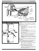
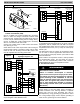
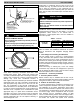
T ransformer is factory wired for 230- v operation. For
208- v applications, disconnect black wire from 230- v
terminal on transformer and connect it to 208- v terminal.
(See Fig. 8.)