
Installation Manual

INST ALLATION INSTRUCTIONS Fan Coils: FCM4X
6 496 01 4201 04
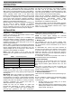
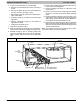
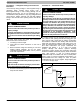
Figure 6 A Coil in Horizontal- Right Application
A00071
COIL
SUPPORT
RAIL
COIL
BRACKET
DRAIN PAN
SUPPORT
BRACKET
COIL
SUPPORT
RAIL
COIL
BRACKET
HORIZONTAL
DRAIN PAN
PRIMARY DRAIN
HORIZONTAL RIGHT
SECONDARY DRAIN
HORIZONTAL RIGHT
REFRIGERANT
CONNECTIONS
AIR SEAL
ASSEMBLY
A
B
C
HORIZONTAL
RIGHT
APPLICATION
F. DOWNFLOW INSTALLATION
!
CAUTION
PRODUCT OR PROPERTY DAMAGE HAZARD
Failure to follow this caution may result in product or
property damage
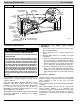
The conversion of the fan coil to downflow requires
special procedures for the condensate drains on both
A - coil and Slope - coil units. The vertical drains have
an overflow hole between the primary and secondary
drain holes. This hole is plugged for all applications
except downflow , and must be used for downflow.
During conversion process, remove plastic cap cov-
ering vertical drains only and discard. Remove plug
from overflow hole and discard. At completion of
downflow installation, caulk around vertical pan fit-
ting to door joint to retain low air leak performance of
the unit.
In this application, field conversion of the evaporator coil is
required using accessory downflow kit along with an
accessory base kit.
NOTE: To convert units for downflow applications, refer to
Installation Instructions supplied with kit for proper
installation. For unit size 36, use kit Part No. EBAC01DFS.
For unit sizes 24, 48, and 60, use kit Part No.
EBAC02DFA. Use fireproof resilient gasket, 1/8- to 1/4- in.
thick, between duct, unit, and floor.
NOTE: Gasket kit number EBAC01GSK is also required for
all downflow applications to maintain low air leak/low
sweat performance.
G. Manufactured and Mobile Home Housing
Applications
1. Fan coil unit must be secured to the structure using
field- supplied hardware.
2. Allow a minimum of 24- in. clearance from access
panels.
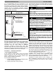
3. Recommended method of securing for typical
applications
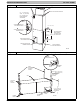
a. If fan coil is away from wall, attach pipe strap to top
of fan coil using No. 10 self tapping screws. Angle
strap down and away from back of fan coil, remove
all slack, and fasten to wall stud of structure using
5/16- in. lag screws. Typical both sides of fan coil.
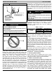
b. If fan coil is against wall, secure fan coil to wall stud
using 1/8- in. thick right- angle brackets. Attach
brackets to fan coil using No. 10 self tapping screws
and to wall stud using 5/16- in. lag screws. (See Fig.
7.)
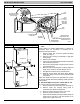
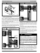
Procedure 3. — Air Ducts
Connect supply- air duct over outside of 3/4- in. flange
provided on supply- air opening. Secure duct to flange with
proper fasteners for type of duct used, and seal
duct- to- unit joint.
Duct connection flanges are provided on unit air discharge
connection.
When using FCM4X units with 20- , 24- , and 30- kW
electric heaters, maintain a 1- in. clearance from
combustible materials to discharge plenum and ductwork
for a distance of 36” / 914.4 mm from unit. Use accessory
downflow base to maintain proper clearance on downflow
installations.