
Installation Manual

INST ALLATION INSTRUCTIONS Fan Coils: FCM4X
14 496 01 4201 04
NOTE: It may be useful as an electric heater
troubleshooting procedure to disconnect the system
communications to force Status Code 16 enabling of
emergency heat mode. It is difficult to know which heater
output is energized or not energized in normal operation.
When fan coil is operated in emergency heat mode using
electric heaters, both outputs are energized and
de- energized together. Terminal strip inputs to control can
then be connected R to W to turn on both electric heat
outputs. Heater output sensing circuits can then be
checked to resolve Status Code 36 or 37 problems.
STATUS CODE 41, BLOWER MOTOR FAULT:
If MOTOR LED is lit and flashing and motor does not run:
1. Check STATUS LED. If STATUS LED is indicating
Status Code 41, motor control has detected that the
motor will not come up to speed within 30 seconds of
being commanded to run or that the motor has been
slowed to below 250 rpm for more than 10 seconds
after coming up to speed. Motor wiring harness and
fan coil control are operating properly, do not replace.
2. Check to be sure that the blower wheel is not rubbing
the housing.
3. Check motor to be sure that the motor shaft is not
seized (motor Control Module must be removed and
electronics disconnected from windings to perform
this check properly).
4. Check motor windings section following instructions in
Section C. ECM Motor T roubleshooting.
If all these checks are normal, the motor Control Module
may need replacement.
STATUS CODE 16, SYSTEM COMMUNICATIO N FAULT:
On initial power- up and at any time system
communications are not successful for a period exceeding
2 minutes following successful communications, the fan
coil control will only allow emergency heating or cooling
operation using a common thermostat, a
non- communicating outdoor unit, and the RGWYO
outdoor unit terminal strip connections and will display
Status code 16 on the amber ST ATUS LED (see section
E, Emergency Heating and Cooling Modes). No further fan
coil troubleshooting information will be available at the Wall
Control until communications are reestablished.
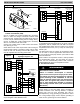
Check system wiring to be sure the Wall Control is
powered and connections are made DX+ to DX+, DX- to
DX- , etc. and wiring is not shorted. Mis- wiring or shorting
of the DX+DX- CR communications wiring will not allow
successful communications. Correcting wiring faults will
clear the code and reestablish communications.
Shorting or mis- wiring the low voltage system wiring will
not cause damage to fan coil control or to Wall Control but
may cause the low voltage fuse to open.
STATUS CODE 46, BROWNOUT CONDITION:
If the secondary voltage of the transformer falls below
15VAC for a period exceeding 4 seconds, Status Code 46
will be displayed on STATUS LED. If system includes a
non- communicating outdoor air conditioner or heat pump,
the W all Control will command the fan coil to turn off Y
output controlling compressor.
When secondary voltage rises above 17VAC for more than
4 seconds, the brownout condition is cleared and normal
system operation will resume subject to any minimum
compressor off delay function which may be in effect.
Brownout does not affect blower or electric heater
operation.
STATUS CODE 53, OUTDOOR AIR TEMPERATURE
SENSOR FAULT:
If an OAT sensor is found at power- up, input is constantly
checked to be within a valid temperature range. If sensor
is found to be open or shorted at any time after initial
validation, Status Code 53 will be displayed at amber
STATUS LED.
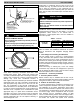
Check for faults in wiring connecting sensor to OAT
terminals. Using an Ohmmeter, check resistance of
thermistor for a short or open condition. If thermistor is
shorted or open, replace it to return the system to normal
operation. If fault is in the wiring connections, correcting
the fault will clear the code and return the system to
normal operation.
NOTE: If fault condition is an open thermistor or a wiring
problem that appears to be an open thermistor and the
power to the fan coil control is cycled off, the fault code will
be cleared on the next power- up but the fault will remain
and system operation will not be as expected. This is
because on power- up, the fan coil control cannot discern
the difference between an open sensor or if a sensor is not
installed.
F. Emergency Heating and Cooling Modes
Fan coil control can provide emergency heating or cooling
using a common heat/cool thermostat in the event that
there are no system communications, fault is in Wall
Control and no replacement is immediately available.
To activate these modes, the thermostat and outdoor unit
must be wired as a common heating/cooling system to fan
coil control RGWYOC terminals.
NOTE: These emergency modes do not provide the level of
comfort and efficiency expected by the consumer and
should only be activated when Wall Control cannot be
replaced immediately.
Procedure 10. — FCM4X Fan Coil Sequence of
Operation
The FCM4X Fan Coil is designed for installation with an
Observer Communicating Wall Control only. This fan coil
will not respond to commands provided by a common
thermostat except under certain emergency situations
described in Procedure 9 - Start Up and Troubleshooting.
The Wall Control uses temperature; humidity and other
data supplied from indoor and outdoor system
components to control heating or cooling system for
optimum comfort. The fan coil will be commanded by W all
Control to supply airflow and, in the case of a
non- communicating outdoor unit, Air Conditioner or Heat
Pump control. The fan coil will operate blower at requested
airflow for most modes.
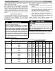
The nominal requested airflow will be 350 cfm per ton of
nominal cooling capacity as defined by outdoor unit size.
Actual airflow request will be adjusted from nominal using
indoor and outdoor temperature and indoor humidity data
to optimize the system operation for occupant comfort and