
Installation Manual

INST ALLATION INSTRUCTIONS Fan Coils: FCM4X
496 01 4201 04 13
1. Stop all system operations at Wall Control and check
heater stage 24VAC outputs.
2. Disconnect electric heater at plug/receptacle 2 and
check heater wiring for faults. See Status Code 36 for
more information.
STATUS CODE 44, MOTOR COMMUNICATION FAULT:
The MOTOR LED is connected to the blower motor
communication line and works with the fan coil control
microprocessor and STATUS LED to provide fan coil
operation and troubleshooting information. When motor is
commanded to operate, the MOTOR LED will be turned on
and will flash each time instructions are sent to the motor.
When the motor is commanded to stop, the MOTOR LED
will be turned off. The MOTOR LED will not flash to
indicate communications when it is turned off.
Fan coil control is constantly communicating with the
motor, even when the motor and MOTOR LED are off. If
motor does not acknowledge receipt of communications,
the control will display Status Code 44 on STATUS LED
and continue to try to communicate with the motor . If
motor acknowledges communication, Status Code will be
cleared.
If MOTOR LED is lit and flashing and motor does not run:
1. Check the ST ATUS LED. If STATUS LED is indicating
a Status 44 code, check the motor wiring harness for
proper connection to control and motor receptacles.
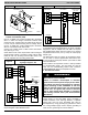
2. Check motor wiring harness to be sure all wiring
complies with wiring diagram description, makes a
complete circuit from connector to connector and is
not shorted.
3. Check 12 Vdc low voltage supply to motor at pins 1 (+)
and 2 (- ) of motor header connection to fan coil
control.
If all checks are normal, fan coil control is good and
Control Module on motor may need replacement. Check
motor and Motor Control Module following the instructions
in Section C. ECM Motor Troubleshooting.
Shorted or mis- wiring of the low voltage motor harness
wiring will not cause damage to fan coil control or to motor
Control Module.
If the MOTOR LED is off, STATUS LED is indicating a
Status Code 44 and motor is running:
Disconnect the motor harness at the fan coil control. If
motor continues to run, fan coil control is good and Control
Module on motor may need replacement.
STATUS CODE 25, INVALID MOTOR / MODEL
SELECTION:
On initial start- up, fan coil control shall poll motor for its
size data and check fan coil size data stored in fan coil
control memory.
1. If motor size is incorrect for fan coil size or fan coil size
data is invalid, Status Code 25 will be displayed on
STATUS LED.
2. If model size data is missing (as is the case when a
replacement fan coil control is installed), syst em Wall
Control will prompt installer to enter correct model size
from a list of valid sizes.
3. If motor size is incorrect for model size, motor must be
replaced with proper size motor. Fan coil control will
not respond to operation requests until this fault
condition is resolved.
STATUS CODE 27, INVALID OUTDOOR UNIT SIZE:
On initial power- up, fan coil control will write into memory
outdoor unit size as provided by W all Control in a fully
communicating system.
1. If outdoor unit size is invalid, Status Code 27 will be
displayed on STATUS LED.
2. Wall Control will prompt the installer to choose size
from a list of valid sizes for application with fan coil.
3. Check communications wiring to be sure Wall Control
has established communications with outdoor unit or
select proper size from valid size list provided at W all
Control.
4. Check motor and motor Control Module following the
instructions in Section C. ECM Motor
T roubleshooting.
STATUS CODE 26, INVALID HEATER SIZE:
On initial power- up, fan coil control will write into memory
electric heater size as read from heater if heater is
provided with Identifier Resistor (IDR). Heater size must
be valid for combination of indoor and outdoor components
installed. Fan coil control will read IDR value connected to
pins 5 and 8 of heater harness connector . If no resistor is
found, system Wall Control will prompt installer to verify
that no heater is installed. Verifying that this is correct will
establish that fan coil is operating without an electric
heater accessory. Upon choosing negative option, installer
will be prompted to select heater size installed from a list
of valid heater sizes for fan coil and outdoor unit size
installed. If heater ID resistor value read is invalid, Status
Code 26 will be displayed on STATUS LED. If heater
installed is equipped with a resistor connected to pins 5
and 8 of heater harness connector and Status Code 26 is
displayed on STATUS LED:
1. Check wiring harness connections to be sure
connections are secure.
2. If symptoms persist, disconnect wiring harness at fan
coil control heater header and check for a resistance
value greater than 5000 ohms.
3. Check for proper wiring of resistor assembly.
4. Make sure heater size installed is an approved size for
outdoor unit and fan coil sizes installed.
NOTE: Fan coil control will not operate electric heater until
this Status Code is resolved. If the heater size is set
through the Wall Control, the heater will be operated as a
single stage heater. If staging is desired, the IDR value
must be read in by the fan coil control.
STATUS CODE 36, HEATER OUTPUT NOT SENSED
WHEN ENERGIZED:
Fan coil control is provided with circuitry to detect
presence of a 24VAC signal on Electric Heater stage 1
and stage 2 outputs. If fan coil control energizes either
heater stage and does not detect the 24VAC signal on
output, Status Code 36 will be displayed on the STATUS
LED Fan coil control will continue to energize heater
output(s) and adjust blower operation to a safe airflow
level for energized electric heat stage(s).
To find the fault:
Check for 24VAC on heater stage outputs. Fan coil control
or sensing circuit may be bad.