
Installation Manual


INST ALLATION INSTRUCTIONS R- 410A Split System Heat Pumps
428 01 5110 00 3
Specifications subject to change without notic e.
Roof mounted units exposed to winds may require wind
baffles. Consult the Low- Ambient pressure switch installation
instructions for wind baffle construction.
NOTE: Unit must be level 2 degrees [3/8 inch rise or fall per
foot of run (10mm rise or fall per 305 mm of run)] or compressor
may not function properly.
Clearance Requirements
When installing, allow sufficient space for airflow clearance,
wiring, refrigerant piping, and service. Allow 24 in. (610 mm)
clearance to service end of unit and 48 in. (1219.2 mm)
above unit. For proper airflow, a 6 in. (152.4 mm) clearance
on one side of unit and 12 in. (304.8 mm) on all remaining
sides must be maintained. Maintain a distance of 24 in.
(609.6 mm) between units or 18 in. (457.2 mm) if no
overhang within 12 ft. (3.66m). Position so water, snow, or ice
from roof or eaves cannot fall directly on unit.
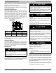
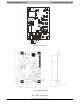
3/8–in. (9.53 mm) Dia.
Tiedown Knockouts in
Basepan(2) Places
View From Top
UNIT BASE PAN
Dimension in. (mm)
TIEDOWN KNOCKOUT LOCATIONS in. (mm)
A B C
31–1/2 X 31–1/2
(800 X 800)
9–1/8 (231.8) 6–9/16 (166.7) 24–11/16 (627.1)
35 X 35
(889 X 889)
9–1/8 (231.8) 6–9/16 (166.7) 28–7/16 (722.3)
A05177
Fig. 2 - Tiedown Knockout Locations
On rooftop applications, locate unit at least 6 in. (152.4 mm)
above roof surface.
Operating Ambient
The minimum outdoor operating ambient in cooling mode is
55°F (12.78_C) without low ambient cooling enabled, and the
maximum outdoor operating ambient in cooling mode is
125°F (51.67_C). The maximum outdoor operating ambient in
heating mode is 66°F (18.89_C)
Elevate Unit
CAUTION
!
UNIT DAMAGE HAZARD
Failure to follow this caution may result in equipment
damage or improper operation.
Unit must be kept free of an accumulation of water and/or
ice in the basepan.
Elevate unit per local climate and code requirements to
provide clearance above estimated snowfall level and ensure
adequate drainage of unit. If using accessory support feet,
use installation instructions from kit for installation.
CAUTION
!
UNIT DAMAGE HAZARD
Failure to follow this caution may result in equipment
damage or improper operation.
To prevent damage to the unit, ensure that it is located
with the supports such that the unit is stable in all
circumstances including adverse conditions.
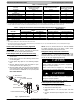
Make Piping Connections
!
WARNING
PERSONAL INJURY AND ENVIRONMENTAL
HAZARD
Failure to follow this warning could result in personal
injury or death.
Relieve pressure and recover all refrigerant before system
repair or final unit disposal.
Use all service ports and open all flow- control devices,
including solenoid valves.
CAUTION
!
UNIT DAMAGE HAZARD
Failure to follow this caution may result in equipment
damage or improper operation.
Do not leave system open to atmosphere any longer than
minimum required for installation. POE oil in compressor is
extremely susceptible to moisture absorption. Always keep
ends of tubing sealed during installation.
If ANY refrigerant tubing is buried, provide a 6 in. (152.4
mm) vertical rise at service valve. Refrigerant tubing
lengths up to 36 in. (914.4 mm) may be buried without
further special consideration. Do not bury lines more than
36 in. (914.4 mm).
!
WARNING
PERSONAL DAMAGE HAZARD
Failure to follow this warning may result in equipment
damage or improper operation.
To prevent damage to unit or service valves, observe the
following:
S Use a brazing shield.
S Wrap service valves with wet cloth or use a heat sink
material.
Outdoor units may be connected to indoor section using
accessory tubing package or field - supplied refrigerant grade
tubing of correct size and condition. For tubing requirements
beyond 80 ft/24.38 m, substantial capacity and performance
losses can occur. Following the recommendations in the
Long Line Applications Guideline will reduce these losses.
Refer to Table 1 for accessory requirements. Refer to Table 2
for field tubing diameters.
If refrigerant tubes or indoor coil are exposed to atmosphere,
they must be evacuated to 500 microns to eliminate
contamination and moisture in the system.