
Specifications
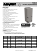


PRODUCT SPECIFICATIONS Fan Coils: FEM4X
496 51 5601 02 9
Specifications are subject to change without notice.
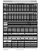
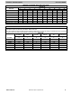
MINIMUM CFM WHEN USING ELECTRIC HEAT
Unit Size
HEATER kW
3 5 8 9 10 15 18 20 24 30
1800B 525 525 525 — 600 — — — — —
2400C 700 700 700 — 700 775 — — — —
3000B — 875 875 — 875 875 — 1060 — —
3600B — 1050 970 970 970 920 — 1040 — —
4200B — — 1225 1225 1225 1225 1225 1225 — —
4800B — — 1400 1400 1400 1400 1400 1400 1400 1400
6000B − − 1750 1750 1750 1750 1750 1750 1750 1750
Note: Speed Tap 4 (white wire) is used for electric heat only. White wire must remain on tap 4.
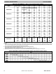
STATIC PRESSURE CORRECTION FOR ELECTRIC HEATERS (inches of water column)
Airflow performance chart was developed using fan coils with 10 kW electric heater (2 elements) in the 1800 − 3600 model sizes, and
15 kW electric heaters (3 elements) in the 4200 − 4800 model sizes.
When using a different number of heater elements, adjust the static pressure numbers by adding or subtracting the values in this table
(for a given CFM, more electric heater elements create higher static pressure drop).
Unit Size
Heater kW
No Heater 3 or 5 8 or 10 9 or 15 20 18, 24, or 30
Number of Heat Elements
0 1 2 3 4 6
1800B +0.02 +0.01 0 −0.02 −0.04 −
2400C +0.02 +0.01 0 −0.02 −0.04 −
3000B +0.02 +0.01 0 −0.02 −0.04 −
3600B +0.02 +0.01 0 −0.02 −0.04 −
4200B +0.04 − +0.02 0 −0.02 −0.10
4800B +0.04 − +0.02 0 −0.02 −0.10
6000B +0.04 − +0.02 0 −0.02 −0.10