
Service Manual


SERVICE AND MAINTENANCE FAN COILS
8 496 08 8001 02
Specifications subject to change without notice.
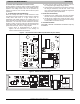
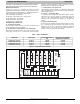
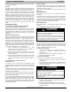
Figure 6 − Easy Select Board Schematic
AUX1
SYSTEM DIAGRAM
HEATER/MOTOR
12
11
10
9
8
7
6
5
4
3
2
1
SEC1 SEC2
5 AMP
J1
D
H
R
W
1
W
2
Y
1
Y/Y
2
G
O
C
J2
HUM1
AUX2
HUM2
DIODE
LOGIC
AUX HEAT
KW/CFM
AC/HP
SIZE
SYSTEM
TYPE
AC/HP CFM
ADJUST
ON/OFF
DELAY
CONTINUOUS
FAN
GRY
1
/
4
"
1
/
4
"
1
/
4
"
1
/
4
"
1
/
4
"
1
/
4
"
1
/
4
"
A96431
Table 2 – FVM4X Connections and Connectors
Type Connection
Type Connector Pin No. Description
Heater Connection 12-Pin
Pin 1 Common to screw terminal G
Pin 2 Common to screw terminal Y/Y2 through diode D3
Pin 3 Common through Y1 through diode D2
Pin 4 Common to W2 screw terminal
Pin 5 Common to W2 screw terminal
Pin 6 Common to W1 screw terminal
Pin 7 Common to W1 screw terminal
Pin 8 R 24Vac
Pin 9 Common to transformer C
Pin 10 Common to transformer C
Pin 11 Common to transformer C
Pin 12 Common to DH screw terminal
Table 3 – Typical Operating Modes
Operating Mode Terminals Energized
Heat Pump Only Heating R, Y/Y2, G, DH
Heat Pump Only Heating + Super Comfort Heat Mode R, Y/Y2, DH
Heat Pump Heating + Auxiliary Heat (non-staged) R, Y/Y2, G, DH, W2
Cooling R, Y/Y2, G, DH, O
Cooling + Dehumidification R, Y/Y2, G, O
Cooling + Superdehumidification R, Y/Y2, O
F. Heat Pump Heating Mode — Single Speed or
Two−Speed High
Thermostat closes R to Y/Y2 and R to G. A circuit R to Y1 is
required for two−speed high operation. The unit delivers
airflow selected by AC/HP SIZE selection and CFM ADJUST
selection. Selected delay profile is active in this mode.
G. Heat Pump Heating Mode — 2−Speed Low
Thermostat closes R to G and R to Y1. Unit delivers
two−speed low airflow for AC/HP SIZE and CFM ADJUST
selected. Selected delay profile is active in this mode.
H. Non−Staged Auxiliary with Heat Pump Heating Mode
Thermostat should already have closed R to G, R to Y2 for
heat pump heating operation. With J2 jumper in place,
energizing either W1 or W2 will produce the W2 airflow. This is
the greater of heat pump heating and auxiliary heat airflow
plus an additional 15 percent. The elected delay profile is not
active in this mode.
I. Staged Auxiliary Heat with Heat Pump Heating Mode
The auxiliary heat can be staged by removing the J2 jumper
that ties W1 and W2 terminals together. Staging can be done
by using outdoor thermostats or by using the heat staging
option where the indoor control can be configured for
three−stage electric heat. The unit will automatically adjust
airflow when the different stages of heat are energized. The
airflow delivered will depend on the heat pump size selected
and electric heat size selected. The greater of the two airflows
will be delivered. The selected delay profile is not active in this
mode.
J. Electric Heat without Heat Pump
Thermostat closes R to W and thermostat should be set up to
energize G with W. This is due to the Super Comfort Heat
programming in the motor. Energizing W without G will result in
25% lower airflow delivery. The selected delay profile is not
active in this mode.