
Service Manual


SERVICE AND MAINTENANCE FAN COILS
496 08 8001 02 25
Specifications subject to change without notice.
vanes. Do not drop or bend wheel as balance will be
affected.
To reassemble unit, proceed as follows:
1. Place motor with mount attached on flat, horizontal
surface with shaft up.
2. Set inlet ring on top of motor mount grommets. Center
inlet ring flush on all three grommets.
3. Slide blower wheel onto motor shaft with setscrew
upward and aligned with shaft flat portion. Vertically
position wheel along shaft to position marked during
disassembly.
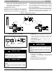
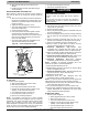
NOTE: If previous shaft was not marked or if replacing
previous motor, set blower wheel position by sliding blower
wheel along motor shaft to 1−1/8−in. above rubber grommets.
(See Figure 20.)
4. Hold blower wheel in place and carefully tighten
setscrew.
5. Position motor and blower wheel assembly to blower
housing as originally oriented.
6. Secure motor mount to blower housing using bolts
previously removed.
7. Attach green wire to blower housing with screw.
8. Connect electrical and capacitor leads to original
terminals.
9. Replace blower access door and tighten all four screws.
10. Reinsert disconnect pullout only after blower access
door is secured. Test blower for proper operation.
Figure 20 − Motor, Inlet Ring, and Blower Wheel Assembly
GROMMET
BLOWER
WHEEL
INLET
RING
MOTOR
1
1
⁄8≤
A86006
REFRIGERANT FLOW−CONTROL DEVICES
Thermostatic Expansion Valves (TXV)
The FSA4X, FEA4X, FEM4X, FXM4X, FCM4X, FVM4,
WAHM, WAHT, WAHL, WAXM, WAXT, WAXL, and REM4X
Fan Coils are factory equipped with a hard shutoff (HSO) TXV.
The hard shutoff TXV has no bleed port and allows no
bleed−through after system is shutdown.
The TXV is a bi−flow metering device that is used in
condensing and heat pump systems to adjust to changing
load conditions by maintaining a preset superheat temperature
at outlet of evaporator coil. The volume of refrigerant metered
through valve seat is dependent upon the following:
1. Superheat temperature sensed by sensing bulb on
suction tube at outlet of evaporator coil. As long as this
bulb contains some liquid refrigerant, this temperature is
converted into pressure pushing downward on the
diaphragm, which opens the valve via push rods.
2. The suction pressure at outlet of evaporator coil is
transferred via the external equalizer tube to underside
of diaphragm.
The bi−flow TXV is used on split system heat pumps. In
cooling mode, TXV operates the same as a standard TXV
previously explained. However, when system is switched to
heating mode of operation, refrigerant flow is reversed.
The bi−flow TXV has an additional internal check valve and
tubing. These additions allow refrigerant to bypass TXV when
refrigerant flow is reversed with only a 1−psig to 2−psig
pressure drop through device.
When heat pump switches to defrost mode, refrigerant flows
through a completely open (not throttled) TXV. The bulb
senses the residual heat of outlet tube of coil that had been
operating in heating mode (about 85_F and 155 psig). This
temporary, not−throttled valve decreases indoor pressure
drop, which in turn increases refrigerant flow rate, decreases
overall defrost time, and enhances defrost efficiency.
PROBLEMS AFFECTING TXV
A. Low Suction Pressure
1. Restriction in TXV
2. Low refrigerant charge
3. Low indoor load
4. Low evaporator airflow
B. High Suction Pressure
1. Overcharging
2. Sensing bulb not secure to vapor tube
3. High indoor load
4. Large evaporator face area
NOTE: When installing or removing TXV, wrap TXV with a wet
cloth. When reattaching TXV, make sure sensing bulb is in
good thermal contact with suction tube.
5. The needle valve on pin carrier is spring−loaded, which
also exerts pressure on underside of diaphragm via
push rods, which closes valve. Therefore, bulb pressure
equals evaporator pressure at outlet of coil plus spring
pressure. If load increases, temperature increases at
bulb, which increases pressure on topside of
diaphragm, which pushes pin carrier away from seal,
opening valve and increasing flow of refrigerant. The
increased refrigerant flow causes increased leaving
evaporator pressure which is transferred via the