
Specifications
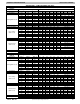
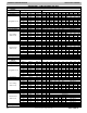

PRODUCT SPECIFICATIONS Gas Furnace: G96VTN
44051480002 3
Specifications subject to change without notice.
PHYSICAL D
A
T
A
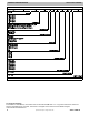
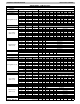
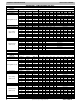
Heating Capacity and Efficiency 0401410 0401712 0601412 0601714 0801716 0802120 1002120 1202422
Input
High Heat (BTUH) 40,000 40,000 60,000 60,000 80,000 80,000 100,000 120,000
Low Heat (BTUH) 26,000 26,000 39,000 39,000 52,000 52,000 65,000 78,000
Output
High Heat (BTUH) 39,000 39,000 58,000 58,000 78,000 78,000 97,000 117,000
Low Heat (BTUH) 25,000 25,000 38,000 38,000 50,000 51,000 63,000 76,000
Certified Temperature
Rise Range ºF (ºC)
High Heat
40 --- 70
( 2 2 --- 3 9 )
40 --- 70
(22 --- 39)
40 --- 70
( 2 2 --- 3 9 )
40 --- 70
(22 --- 39)
40 --- 70
( 2 2 --- 3 9 )
40 --- 70
(22 --- 39)
40 --- 70
( 2 2 --- 3 9 )
40 --- 70
(22 --- 39)
Low Heat
30 --- 60
( 1 7 --- 3 3 )
30 --- 60
(17 --- 33)
30 --- 60
( 1 7 --- 3 3 )
30 --- 60
(17 --- 33)
30 --- 60
( 1 7 --- 3 3 )
30 --- 60
(17 --- 33)
30 --- 60
( 1 7 --- 3 3 )
30 --- 60
(17 --- 33)
Airflow Capacity and Blower Data
Rated External Static
Pressure (in. w.c.)
Heating 0.10 0.10 0.12 0.12 0.15 0.15 0.20 0.20
Cooling 0.50 0.50 0.50 0.50 0.50 0.50 0.50 0.50
Airflow Delivery
@RatedESP(CFM)
High Heat 800 850 1110 1135 1450 1555 1865 2120
Low Heat 560 625 770 860 1130 1200 1435 1625
Cooling 1030 1105 1115 1475 1655 2005 2005 2190
Cooling Capacity (tons)
@ 400, 350 CFM/ton
400 CFM/ton 2 2.50 2.50 3.50 4 5 5 5
350 CFM/ton 2.50 3 3 4 4.50 5.50 5.50 6
Direct---Drive Motor Type Electronically Communicated Motor (ECM)
Direct---Drive Motor HP 1/2 1/2 1/2 3/4 3/4 1 1 1
Motor Full Load
A
mps Default
/
Low
A
mp Kit{ 6.30 6.50 6.30 10.10 9.20 13.9/10.4 13.9/10.4 11.7
RPM Range
600 ---
2000
400 ---
1200
600 ---
2000
400 ---
1200
400 ---
1200
400 ---
1200
400 ---
1200
400 ---
1200
Speed Selections
V
ariable (PWM)
Blower Wheel Dia x Width in. 11
x
7 11
x
8 11
x
7 11
x
8 11 x 8 11 x 10 11
x
10 11
x
11
A
ir Filtration System
Optional Media Cabinet
FieldSuppliedFilter
Filter Used for Certified Watt Data NAHA00*06FB
Electrical Data
Input Voltage Vo l t s --- H e r t z --- P h a s e 1 1 5 --- 6 0 --- 1
Operating Voltage Range Min---Max 104---127
Maximum Input
A
mps Default
/
Low
A
mp Kit{
A
mps 7.0 7.2 7.1 10.9 10.0 14.7/11.3 14 .7/11.3 12.6
Unit
A
mpacity Default
/
Low
A
mp Kit{
A
mps 9.70 9.80 9.70 14.60 13.40 19.3/14.9 19.4/15.0 16.7
Minimum Wire Size Default
/
Low
A
mp Kit{
A
WG 14 14 14 14 14 12/14 12/14 12
Maximum Wire Length
@ Minimum Wire Size Default / Low Amp Kit {
Feet 38 37 38 25 27 29/24 29/24 34
(M) (11.7) (11.5) (11.7) (7.7) (8.4) (9.0/7.5) (9.0/7.5) (10.5)
M a x i m um Fu s e / C k t B k r ( Tim e --- D e l a y Ty p e
Recommended)Default / Low Amp Kit{
A
mps 15 15 15 15 15 20/15 20/15 20
Transformer Capacity (24vac output)
V
A
External Control Power
Available
Heating 24.3
V
A
Cooling 34.6
V
A
Controls
Gas Connection Size 1/2” --- NPT
Burners (Monoport) 2 2 3 3 4 4 5 6
Gas Valve (Redundant) Manufacturer White Rodgers
Minimum Inlet Gas pressure (in. wc) 4.50
Maximum Inlet Gas pressure (in. wc) 13.60
Manufactured (Mobile) Home Kit not approved for MH use
Ignition Device Silicon Nitride
Heating Blower Control (Heating O
f
f
--- D e l a y )
A
djustable: 90 , 120, 150, 180 seconds
Cooling Blower Control (Time Delay Relay) 90 seconds
Communication System None
Thermostat Connections R, W/W1, W2
Y
/Y2,
Y
1, G, Com 24V, DHUM
A
ccessory Connections EAC (115vac); HUM (24vac); 1 ---stg.
A
C(via
Y
/Y2)
{ Low Amp Kit (NAHA00101PC) allows select furnaces to be installed with a 15 Amp Breaker and 14 AWG wire within the listed wire length.
Affected data shown as Default Value/Value with Lower Amp Kit.