
Installation Manual


32 440 01 4800 02
Specifications subject to change without notice.
A190044
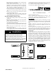
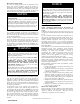
Fig. 38 -- Example of Variable Speed Furnace Control
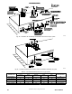
Accessories (See Fig. 37 and 38.)
1. Electronic Air Cleaner (EAC)
Connect an accessory Electronic Air Cleaner (if used) using
1/4--in. female quick connect terminals to the two male
1/4--in. quick-- connect terminals on the control board
marked EAC--1 and EAC--2. The terminals are rated for
115VAC, 1.0 amps maximum and are energized during
blower motor operation.
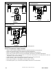
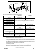
Connect an accessory 24 VAC, 0.5 amp. maximum humidifier (if
used) to the ¼--in. male quick--connect HUM terminal and
COM--24V screw terminal on the control board thermostat strip.
NOTE: If the humidifier has its own 24 VAC power supply, an
isolation relay may be required. Connect the 24 VAC coil of the
isolation relay to the HUM and COM/24V screw terminal on the
control board thermostat strip. See Fig. 37.
2. Humidifier (HUM)
The HUM terminal is a 24 VAC output, ener gized when the blower
is operating during a call for heat.
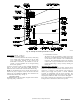
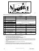
3. Communication Connector
The furnace can only be controlled by a single or two-- stage
thermostat. A Communicating User Interface will not oper-
ate this furnace when connected to the Communication
Connector. The Communication Connector on the furnace
control board is only for communication between furnaces
twinned together using a factory accessory twinning kit.
See Fig. 38.
Alternate Power Supplies
This furnace is designed to operate on utility generated power
which has a smooth sinusoidal waveform. If the furnace is to be
operated on a generator or other alternate power supply, the
alternate power supply must produce a smooth sinusoidal
waveform for compatibility with the furnace electronics. The
alternate power supply must generate the same voltage, phase, and
frequency (Hz) as shown in Table 11 or the furnace rating plate.
Power from an alternate power supply that is non-sinusoidal may
damage the furnace electronics or cause erratic operation.