
Installation Manual

440 01 4800 02 27
Specifications subject to change without notice.
A11338
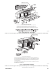
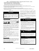
Fig. 29 -- Gas Entry
1ï1/2 inch for Gas
7/8 inch for 115 VAC Electric
A170125
Fig. 30 -- Alternate Gas and Electric Entry
NOTE: Top plate may be field drilled for alternate gas and
1 15 VAC electric entry.
Gas piping must be installed in accordance with national and local
codes. Refer to current edition of NFGC in the USA. Refer to
current edition of NSCNGPIC in Canada.
Installations must be made in accordance with all authorities
having jurisdiction. If possible, the gas supply line should be a
separate line running directly from meter to furnace.
NOTE: Use a back-- up wrench on the inlet of the gas valve when
connecting the gas line to the gas valve.
The gas supply pressure shall be within the maximum and
minimum inlet supply pressures marked on the rating plate with
the furnace burners ON and OFF.
Refer to Table 10 for recommended gas pipe sizing. Risers must be
used to connect to furnace and to meter. Support all gas piping
with appropriate straps, hangers, etc. Use a minimum of one hanger
every 6 ft. (2 M). Joint compound (pipe dope) should be applied
sparingly and only to male threads of joints. Pipe dope must be
resistant to the action of propane gas.
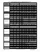
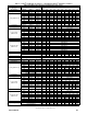
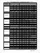
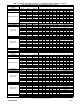
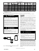
Table 10 – Maximum Capacity o f Pipe
NOMINAL
IRON PIPE
SIZE
IN. (MM)
LENGTH OF PIPE --- FT (M)
10
(3.0)
20
(6.0)
30
(9.1)
40
(12.1)
50
(15.2)
1/2 (13) 175 120 97 82 73
3/4 (19) 360 250 200 170 151
1 ( 25) 680 465 375 320 285
1-1/4 (32) 1400 950 770 660 580
1-1/2 (39) 2100 1460 1180 990 900
* Cubic ft of gas per hr for gas pressures of 0.5 psig (14--- In. W.C.) or less and
a pressure drop of 0.5--- In. W.C. (based on a 0.60 specific gravity gas). Ref:
Table 10 above and 6.2 of current edition of NFPA54/ANSI Z223.1.
Gas Pressure Natural (in W.C.) Propane (in W.C.)
Maximum 13.8
Minimum 4.5” 12”
When a flexible connector is used, black pipe shall be installed at
the furnace gas control valve and extend a minimum of 2-- in. (51
mm) outside the furnace.
For direct vent (2-- pipe) applications, seal the gas pipe knockout to
prevent air leakage.
Remove the required knockout. Install the grommet in the
knockout. Then insert the gas pipe. The grommet is included in
the loose parts bag.
Piping should be pressure and leak tested in accordance with the
current addition of the NFGC in the United States, local, and
national plumbing and gas codes before the furnace has been
connected.
Refer to current edition of NSCNGPIC in Canada. After all
connections have been made, purge lines and check for leakage at
furnace prior to operating furnace.
PRESSURE TESTING ABOVE ½ psig:
The furnace and it’s individual shut--off valve must be
disconnected from the gas supply piping system during any
pressure testing of that system at test pressures in excess of ½ psig
(3.5 kPa).
PRESSURE TESTING BELOW ½ psig:
The furnace must be isolated from the gas supply piping by closing
its individual manual shut-- off valve during any pressure testing of
the gas supply piping system at test pressures equal to or less than
½ psig (3.5 kPa).
FIRE OR EXPLOSION HAZARD
A failure to follow this warning could result in personal
injury, death, and/or property damage.
If local codes allow the use of a flexible gas appliance
connector, always use a new listed connector. Do not use a
connector which has previously served another gas
appliance. Black iron pipe shall be installed at the furnace
gas control valve and extend a minimum of 2 --in. (51 mm)
outside the furnace.
!
WARNING
An accessible manual equipment shutoff valve MUST be installed
external to furnace casing and within 6 ft. (2 M) of furnace.
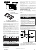
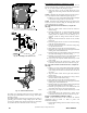
Install a sediment trap externally in the riser leading to furnace as
shown in Fig. 31. Connect a capped nipple into lower end of tee.
Capped nipple should extend below level of furnace gas controls.
Place a ground joint union between furnace gas control valve and
exterior manual equipment gas shutoff valve.
A11035
Fig. 31 -- Typical Gas Pipe Arrangement
A 1/8-- in. (3 mm) NPT plugged tapping, accessible for test gauge
connection, MUST be installed immediately upstream of gas
supply connection to furnace and downstream of manual
equipment shutoff valve.