
Product Specifications


PRODUCT SPECIFICATIONS Gas Furnace: G80CTL
4 441 51 3500 01
Specifications subject to change without notice.
PHYSICAL DATA (CONTINUED)
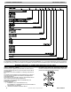
Unit Size 0901716 0902120 1102120 1352422
RATINGS AND PERFORMANCE
Input Btuh*
Nonweatherized ICS
All Standard, Low Nox
Upflow
High 88,000 88,000 110,000 132,000
Low 58,000 58,000 72,500 87,000
Input Btuh*
Nonweatherized ICS
All Low NOx Downflow/
Horizontal
High 84,000 84,000 105,000 126,000
Low 58,000 58,000 72,500 87,000
Output Capacity (Btuh)
Nonweatherized ICS^
All Standard, Low Nox
Upflow
High 71,000 71,000 89,000 107,000
Low 47,000 47,000 59,000 70,000
Output Capacity (Btuh)
Nonweatherized ICS^
All Low NOx Downflow/
Horizontal
High 68,000 68,000 85,000 102,000
Low 47,000 47,000 59,000 70,000
AFUE 80.00
Certified Temperature Rise Range - °F (°C)
High
40-70
(22-39)
25-55
(14-30)
40-70
(22-39)
40-70
(22-39)
Low
30-60
(17-33)
15-45
(8-25)
25-55
(14-31)
25-55
(14-31)
Certified External Static Pressure Heat/Cool 0.15/0.50 0.15/0.50 0.20/0.50 0.20/0.50
Airflow CFM ‡
Heating High/Low 1195/960 1600/1435 1465/1295 1835/1660
Max Cooling 1595 2330 2155 2265
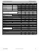
ELECTRICAL
Unit Volts-Hertz-Phase 115-60-1
Operating Voltage Range Min/Max 104/127
Maximum Unit Amps 9.60 14.70 15.00 15.00
Maximum Wire Length (Measure 1 Way in Ft. (M)) 29 (9.0) 30 (9.2) 29 (9.1) 29 (9.1)
Minimum Wire Size 14 12 12 12
Maximum Fuse or Ckt Bkr Size (Amps)** 15 20 20 20
Transformer (24v) 40va
External Control Heating 12va
Power Available Cooling 35va
Air Conditioning Blower Relay Standard
CONTROLS
Limit Control SPST
Heating Blower Control Solid State Time Operation
Burners (Monoport) 4 4 5 6
Gas Connection Size 1/2in. NPT
GAS CONTROLS
Gas Valve
(Redundant)
Mfr. WhiteRodgers
Min. inlet pressure (In. W.C.) 4.5 (Natural Gas)
Max. inlet pressure (In. W.C.) 13.6 (Natural Gas)
Ignition Device Hot Surface
Factory installed orifice Size 43
BLOWER DATA
Direct-Drive Motor HP (ECM) 1/2 1 1 1
Motor Full Load Amps 7.7 12.8 12.8 12.8
RPM (Nominal) 1200 1200 1200 1200
Blower Wheel Diameter x Width - In. (mm)
10 x 8
(254x203)
11 x 11
(279x279)
11 x 10
(254x279)
11 x 11
(279x279)
* Gas input ratings are certified for elevations to 2000 ft. (610 M) In USA for elevations above 2000 ft (610 M), reduce ratings 4 percent for each 1000 ft (305 M) above sea
level. Refer to National Fuel Gas Code NFPA 54/ANSI Z223.1 Table F.4 or furnace installation instructions.
† Capacity in accordance with U.S. Government DOE test procedures.
‡ Airflow shown is for bottom only returnair supply for Max Cooling Airflow and heating airflows (efficiency setting) at certified external static pressure. For air delivery
above 1800 CFM, see Air Delivery table for other options. A filter is required for each return air supply. An airflow reduction of up to 7 percent may occur.
** Time-delay type is recommended.
ICS Isolated Combustion System