
Service Manual


SERVICE AND MAINTENANCE FAN COILS
496 08 8001 02 23
Specifications subject to change without notice.
Because this is a thermally−activated device, ambient
conditions affect the ON/OFF cycle. Higher ambient
temperature means shorter ON times and longer OFF times.
Application of these devices is such that the first switch ON
not only turns on first heater element, but also ensures that
indoor fan is energized, because first ON is last OFF. This
ensures fan remains ON until the last heater de-energizes.
C. Relays
Later production EHK2 heaters have relays controlling the
heater elements instead of sequencers. A small rectifier PCB
is mounted to each relay which converts the incoming 24 VAC
control signal to DC.
In addition to the rectifier circuit, the second and third stage
relays contain a time−on delay circuit of five seconds for
second stage, and eight seconds for third stage. When the
control signal is removed from the relays, all relays will open
with no time−off delay.
CARE AND MAINTENANCE
FEM4, FCM4, FXM4, FVM4, WAP, WAH,
WAX, REM4
To continue high performance, and minimize possible
equipment failure, it is essential periodic maintenance be
performed on this equipment.
The ability to properly perform maintenance on this equipment
requires certain mechanical skills and tools. The only
consumer service recommended or required is filter
maintenance. (See Filter Assembly.)
ELECTRICAL SHOCK HAZARD
Failure to follow this warning could result in personal
injury or death.
Disconnect all power to the unit before servicing the field
wires or removing the control package. The disconnect
(when used) on the access panel does not disconnect
power to the line side of the disconnect, but does allow
safe service to all other parts of the unit.
!
WARNING
The minimum maintenance requirements for this equipment
are as follows:
1. Inspect and clean or replace air filter each month or as
required.
2. Inspect cooling coil, drain pan, and condensate drain
each cooling season for cleanliness. Clean as
necessary.
3. Inspect blower motor and wheel for cleanliness each
heating and cooling season. Clean as necessary.
4. Inspect electrical connections for tightness and controls
for proper operation each heating and cooling season.
Service as necessary.
CUT HAZARD
Failure to follow this caution may result in personal injury.
Sheet metal parts may have sharp edges or burrs. Use
care and wear appropriate protective clothing and gloves
when handling parts.
CAUTION
!
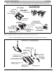
FILTER ASSEMBLY
To clean or replace air filter, push plastic connectors toward
center of unit and remove filter access panel outward. Push
filter up and back into unit. Then slide filter out.
Clean filter by using cold water and mild detergent. Rinse and
allow filter to dry. No oiling or coating of filter is required.
New filters are available from your local distributor. Place filter
in slot with cross−mesh binding up or facing cooling coil and
replace filter access panel.
COOLING COIL, DRAIN PAN, AND CONDENSATE DRAIN
The cooling coil is easily cleaned when it is dry. Inspect the
coil and clean (if necessary) before each cooling season. To
check or clean cooling coil, remove coil access panel. If coil is
coated with dirt or lint, vacuum it with a soft brush attachment.
Be careful not to bend coil fins. If coil is coated with oil or
grease, clean it with a mild detergent and water solution. Rinse
coil thoroughly with clear water. Be careful not to splash water
on insulation.
Inspect drain pan and condensate drain at the same time
cooling coil is checked. Clean drain pan and condensate drain
by removing any foreign matter from pan. Flush pan and drain
tube with clear water.
If drain tube is restricted, it can generally be cleared by
high−pressure water. Cut plastic line and work outside
condensate pan and away from coil to clean drain tube.
UNIT DAMAGE HAZARD
Failure to follow this caution may result in equipment
damage.
Do not use caustic household drain cleaners in the
condensate pan or near the coil. Drain cleaners can
quickly destroy a coil.
CAUTION
!
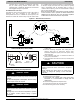
BLOWER MOTOR AND WHEEL
Clean blower motor and wheel when cooling coil is cleaned.
ELECTRICAL SHOCK HAZARD
Failure to follow this warning could result in personal
injury or death.
Disconnect electrical power before removing any
access panels. Lock out and tag switch with a suitable
warning label.
!
WARNING
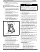
To clean blower motor or blower wheel:
1. Remove blower access panel.
2. Remove motor leads from fan coil control. Note lead
location for ease of reassembly.
3. Remove the two outside screws holding blower/motor
assembly against blower deck flange and slide
assembly out of cabinet.
4. (If applicable) Remove screw in strap holding motor
capacitor to blower housing and slide capacitor out from
under strap. Remove screw with green wire from blower
housing. Mark blower wheel, motor, and motor support
in relation to blower housing before disassembly to
ensure proper reassembly. Note position of blades on
wheel.
5. Loosen setscrew holding blower wheel onto motor shaft.