
Service Manual


SERVICE AND MAINTENANCE FAN COILS
18 496 08 8001 02
Specifications subject to change without notice.
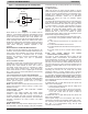
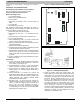
Figure 12 − 18 & 24 PCB
A150462
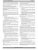
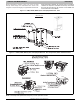
Figure 13 − 30 & 36 PCB
A150463
A. Limit Switch
Refer to Electric Heater Kit Function and Troubleshooting
section of this manual.
B. Sequencer
Early EHK2 heater kits include sequencers instead of relays.
Refer to Electric Heater Kit Function and Troubleshooting
section of this manual.
C. Transformer
A 40−VA transformer supplies 24−V power for control circuit.
Check for 208/230V on primary side of transformer. If present,
check for 24V on secondary side.
NOTE: Transformer is fused. Do not short circuit.
D. Fan Relay
Later EHK2 heater kits include sequencers instead of relays.
Relay coil is 24−V. Check for proper control voltage. Replace
relay if faulty.
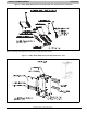
CLEANING OR REPLACING REFRIGERANT
FLOW−CONTROL DEVICE
FMA4P, WAMA
The FMA4P and WAMA piston can be removed and cleaned if
believed to be plugged. This unit’s piston is unique and
replacements are available from FAST.
The filter drier should be located on the liquid line at the indoor
unit to prevent particulate from plugging the piston.
FMA4X, WAXA
The FMA4X and WAXA fan coils use an R−410A TXV. The
TXV’s are preset at the factory and do not need adjustment for
reliable operation. Reference the outdoor unit instructions to
properly charge the unit to the correct subcooling. For optimal
performance, adjust the TXV so that 6º F of superheat is
measured at the outdoor unit’s vapor service valve when the
indoor return air is 80º F DB/67º F WB and outdoor ambient is
82º F DB. To increase superheat turn the TXV adjustment
stem clockwise no more than one rotation at a time. After an
adjustment is made, wait until the superheat temperature has
been stable for 15 minutes before making further adjustments.
SEQUENCE OF OPERATION
A. Condensing Unit
COOLING
When thermostat calls for cooling, the circuit between R and G
is complete and single−pole single−throw relay FR is
energized. The normally open contacts close causing blower
to operate.
The circuit between R and Y is also complete. This completed
circuit causes contactor in outdoor unit to close which starts
compressor and outdoor fan. When thermostat is satisfied, its
contacts open de−energizing contactor and blower relay. This
stops compressor and outdoor fan motor. The indoor fan
motor will stop after 90−100 seconds on the FMA4P and 30 or
90 seconds on the FMA4X.
HEATING
When thermostat calls for heating and FAN switch is set on
AUTO, the circuit between R and W is complete. The heater
sequence SEQ is energized which closes contacts of relay.
There will be a time delay. This completed circuit energizes all
heating elements HTR and blower motor. When thermostat is
satisfied, its contacts open de−energizing contactor and
blower relay. This stops compressor and outdoor fan motor.
The indoor fan motor will stop after 90−100 seconds on the
FMA4P and 30 or 90 seconds on the FMA4X.
B. Heat Pump
COOLING
On a call for cooling, the thermostat makes circuits R−O, R−Y,
and R−G. Circuit R−O energizes reversing valve, switching it
to cooling position. Circuit R−Y energizes contactor starting
outdoor fan motor and compressor. Circuit R−G energizes
indoor unit blower relay starting indoor blower motor.
When thermostat is satisfied, its contacts open de−energizing
contactor reversing valve and blower relay. This stops
compressor and outdoor fan motor.
HEATING
On a call for heating, the thermostat makes circuits R−Y and
R−G. Circuit R−Y energizes contactor starting outdoor fan
motor and compressor. Circuit R−G energizes indoor blower
relay starting blower motor.