
Service Manual


SERVICE AND MAINTENANCE FAN COILS
496 08 8001 02 17
Specifications subject to change without notice.
FMA4P, WAMA, FMA4X, WAXA
ELECTRICAL OPERATION HAZARD
Failure to follow this warning could result in personal
injury or death.
Before installation or servicing system, always turn off
main power to system. There may be more than one
disconnect switch. Turn off accessory heater power if
applicable. Lock out and tag switch with a suitable
warning label.
!
WARNING
FAN MOTOR
FMA4P, WAMA
The FMA4P and WAMA motor is three−speed ECM direct
drive. High−speed lead is black, medium−speed lead is red,
low−speed lead is blue, and common lead is purple. Be sure
proper blower speed has been selected.
The motor is turned on through two different routes. The first
occurs when thermostat calls for the fan in cooling, heat pump,
or fan−only mode. A 24−Vac signal is sent to relay, causing
relay to close its normally open contacts, turning fan on.
The second occurs when there is a call for electric heat. A
24−Vac signal is sent to heater sequencer/relay, causing it to
close, directing 230V through the normally closed contact of
fan relay, turning fan on. The fan remains on until
sequencer/relay opens.
If motor does not run, test motor for an open winding or a
winding shorted to motor case. If either is present, replace
motor.
FMA4X, WAXA
The FMA4X and WAXA motor is five−speed direct drive. The
cooling speed tap is selected by connecting the green wire to
the desired motor tap number indicated on the motor plug. For
the electric heat fan speed selection connect the white wire to
the desired motor tap number indicated on the motor plug.
The blower motor in this unit has blower−on and blower−off
delays. The blower−on delay is 0−30 seconds and will keep
the motor running after a heating or cooling call ends.
If motor does not run, test motor for an open winding or a
winding shorted to motor case. If either is present, replace
motor.
ELECTRIC HEATER SERVICE
Service can be completed with heater in place. Shut off power
before servicing.
TIME DELAY
FMA4X have time delay built into the motor logic. FMA4P units
with date codes prior to V1515 have sequencers. FMA4P units
with date codes V1515 or later have a time delay printed
circuit board.
The Time Delay Printed Circuit Board (PCB) is a logic
controlled time delay activated by low−voltage control signal
(G) from thermostat. The PCB includes a normally open relay
which closes to energize the blower motor when the G
terminal is energized. When the G terminal is de−energized
the relay energizing the blower motor remains closed for
90−100 seconds before opening.
SEQUENCE OF OPERATION
NOTE: The following sequence of operation is based on units
installed with PSC motor and Time Delay Printed Circuit Board
(PCB), See Figure 11, Figure 12 and Figure 13. For units with
ECM motor, the off−delay is programmed into the motor.
Follow Table 6 below, ECM Motor Speed Taps & the
corresponding blower off delay’s for each speed tap.
A. Continuous Fan
Thermostat closes R to G. G energizes and completes circuit
to indoor blower motor. When G is de*energized, there is a
90s blower off−delay.
B. Cooling Mode
Thermostat energizes R to G, R to Y, and R to O (heat pump
only). G energizes and completes indoor blower motor. Y
energizes outdoor unit (O is energized for heat pump). When
cooling call is satisfied, G is de*energized, there is a 90s
blower off−delay.
C. Heat Pump Heating Mode
Thermostat energizes R to G and R to Y. G energizes and
completes circuit to indoor blower motor. When heating call is
satisfied, G is de*energized, there is a 90s blower off−delay.
D. Heat Pump Heating with Auxiliary Electric Heat
Thermostat energizes R to G, R to Y, and R to W1. G
energizes and completes circuit to indoor blower motor. W1
energizes electric heat relay(s) which completes circuit to
heater element(s). When W1 is de*energized, electric heat
relay(s) open, turning off heater elements. When G is
de*energized there is a 90s blower off−delay.
E. Electric Heat or Emergency Heat Mode
Thermostat closes R to W1. W1 energizes electric heat
relay(s) which completes circuit to heater element(s). Blower
motor is energized through normally closed contacts on fan
relay. When W1 is de*energized, electric heat relay(s) opens,
there is no blower off−delay. (units with ECM motor will have a
blower off delay based on motor speed tap selection).
Table 6 – Speed Tap and Delay−Off Time
Speed Tap
Delay−Off Time
Tap 1 30
Tap 2 90
Tap 3 30
Tap 4 90
Tap 5 30
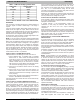
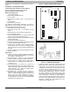
Figure 11 − Time Delay PCB Schematic
Comments:
1. The THR and THC are connect to transformer output:
2. When the G has signal. The FAN will supply 24VAC power to
control fan relay
3. When the G signal gone. The FAN will stop 24 VAC output after
90 seconds.
4. CN3, CN7 are dummy connection terminals.
A150455