
Service Manual


SERVICE AND MAINTENANCE FAN COILS
16 496 08 8001 02
Specifications subject to change without notice.
components to control heating or cooling system for optimum
comfort.
ADVANCED TROUBLESHOOTING:
Troubleshooting the FCM4 Fan Coil Circuit Board:
The circuit board Fan Coil part number 1184554
Primary test that should be performed:
Motor Line Voltage Check
1. Turn off power (240V).
2. Remove Plug 3 from ECM motor
3. Turn on power.
4. Check Plug 3, terminals 4 and 5, to ensure there are
240V.
5. Turn off power.
6. Reconnect Plug 3 to motor.
The following troubleshooting techniques will assist in
determining the correct component to replace when the Fan
Coil Board presents a Fault Code 44 or 41:
1. Disconnect power from the unit (240V).
2. Disconnect the DX+, DX−, C, R connector from the
board.
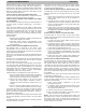
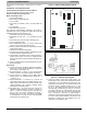
3. Disconnect Plug 1 from the board. (See Figure 10.)
4. Turn on power (240 volts).
5. After reestablishing power, you should receive Fault
Code 44, and the motor LED should be off.
6. Place a jumper across the R and G terminals on the low
voltage terminal block
7. Fault Code 44 should still be flashing.
8. The Motor LED should be flashing, indicating the board
is able to transmit a signal to the motor.
9. If Motor LED is not flashing, check to ensure that 24V is
present across R and C on the low voltage terminal
block and that there is a good connection with the R and
G jumper.
10. If 24V is present and the jumper/connections are good,
11. Replace the board.
Check Board
12. If Fault Code 44 and the Motor LED are both flashing,
place a DC voltmeter across terminals PL1-1 Red (+) to
PL1-2 Green (-). (See Figure 10.)
13. Across terminal PL1−1 and PL1−2, a 12−Vdc should be
present. If 12Vdc is not present, replace circuit board.
14. If Fault Code 44 is flashing and the Motor LED is
flashing, place a DC voltmeter across terminal PL1−3
(+) and PL1−2 (−).
15. Across terminal PL1−3 (+) and PL1−2 (−), the DC volt
meter should display 5Vdc. The voltage should be very
stable and should not fluctuate more than .02Vdc. If the
voltage fluctuates, get a different voltmeter before
proceeding to the following steps.
16. Reconnect Plug 1 to circuit board and connect DC
voltmeter across terminals PL1−3 Yellow (+) and PL1−2
Green (−). Does the voltage appear to fluctuate more
than in step 15? Typical voltmeters will show a
fluctuation of .2Vdc to 1Vdc. The amount of fluctuation
is not important. You could see even more fluctuation
depending on the voltmeter used.
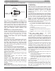
Figure 9 − FCM4 Circuit Board LED Locations
SECï1SECï2
FUSE 3AMP
HEATER
STATUS
COMM
MOTOR
HPT
OPN
COM
CLS
G
W
R
C
HUM
Y
O
DX+DXï C R
A13031
Figure 10 − ECM/Plug Wiring Diagram
17. Check the blower motor serial output signal. The
blinking LED on the control board represents the serial
output signal. You can measure the signal with a DC
voltmeter by removing Plug 1 from the circuit board and
connecting the DC voltmeter across PL1−4 (+) and
PL1−2 (−). The voltage should be near 0Vdc but it will
fluctuate briefly several times per second. If you have
an analog voltmeter, the needle briefly will go high
several times per second. If you have a digital voltmeter
with a bar graph, it will show a large change in
magnitude on the bar graph several times per second. If
you have a plain, digital voltmeter, it will show a brief
fluctuation in voltage, and the magnitude may vary
depending on the voltmeter used.