
N4A6 Product Specs


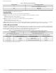
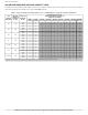


Table Of Contents
- Product Specifications
- Industry leading Features / Benefits
- Efficiency
- Reliability
- Durability
- Applications
- AHRI Ratings
- Product Number Nomenclature
- Physical Data 1-Phase
- Physical Data 3-Phase
- * Units are rated with 25 ft (7.6 m) of lineset length. See Vapor Line Sizing and Cooling Capacity Loss table when using other sizes and lengths of lineset. Note: See unit Installation Instruction for proper installation.
- { See Liquid Line Sizing For Cooling Only Systems with R-410A Refrigerant tables.
- Liquid Line Sizing and Maximum Total Equivalent Lengths{ for Cooling Only Systems with R-410A Refrigerant:
- Table 1 – Maximum Total Equivalent Length Outdoor Unit BELOW Indoor Unit
- *Maximum actual length not to exceed 200 ft (61 m)
- {Total equivalent length accounts for losses due to elbows or fitting. See the Long Line Guideline for details.
- -- = outside acceptable range
- * Maximum actual length not to exceed 200 ft (61 m)
- {Total equivalent length accounts for losses due to elbows or fitting. See the Long Line Guideline for details.
- -- = outside acceptable range
- Charging Formula:
- Long Line Applications
- Note: See Residential Piping and Long Line Guideline for details
- Applications in this area may be long line and may have height restrictions. See the Residential Piping and Long Line Guideline.
- * For tubing line sets between 80 and 200 ft. (24.38 and 60.96 m) and/or 35 ft. (10.7 m) vertical differential, refer to Residential Split-System Longline Application Guideline.
- { Additional requirement for Low-Ambient Controller (full modulation feature) MotorMasterr Control.
- } If unit equipped with ECM OD motor, both motor and fan need to be replaced per unit accessory guide to work properly. Unit will not meet AHRI rated efficiency once motor and fan are replaced to use this accessory.
- Accessory Description and Usage (Listed Alphabetically)
- Accessory Description and Usage (Listed Alphabetically) (Continued)
- Electrical Data
- * Permissible limits of the voltage range at which the unit will operate satisfactorily
- { Time-Delay fuse.
- FLA - Full Load Amps
- LRA - Locked Rotor Amps
- MCA - Minimum Circuit Amps
- RLA - Rated Load Amps
- NOTE: Control circuit is 24V on all units and requires external power source. Copper wire must be used from service disconnect to unit. All motors/compressors contain internal overload protection.
- Complies with 2010 requirements of ASHRAE Standards 90.1
- NOTE: Tested in compliance with AHRI 270–1995 (not listed with AHRI)
- * TXV must be ordered separately when indoor coil is not equipped with a TXV. TXV must be hard–shutoff type.
- IMPORTANT: When installing multiple units in an alcove, roof well, or partially enclosed area, ensure there is adequate ventilation to prevent re-circulation of discharge air.
- Detailed Cooling Capacities#
- Detailed Cooling Capacities# continued
- Detailed Cooling Capacities# continued
- Detailed Cooling Capacities# continued
- Detailed Cooling Capacities# continued
- { Total and sensible capacities are net capacities. Blower motor heat has been subtracted.
- } Sensible capacities shown are based on 80_F (27_C) entering air at the indoor coil. For sensible capacities at other than 80_F (27_C), deduct 835 Btuh (245 kW) per 1000 CFM (480 L/S) of indoor coil air for each degree below 80_F (27_C), or add 835 ...
- # Detailed cooling capacities are based on indoor and outdoor unit at the same elevation per AHRI standard 210/240-2008. If additional tubing length and/or indoor unit is located above outdoor unit, a slight variation in capacity may occur.
- ** System kw is total of indoor and outdoor unit kilowatts.
- {{ At TVA rating indoor condition (75_F edb/63_F ewb). All other indoor air temperatures are at 80_F edb.
- NOTE: When the required data falls between the published data, interpolation may be performed. Extrapolation is not an acceptable practice.
- EWB — Entering Wet Bulb
- * AHRI listing applies only to systems shown in Combination Ratings table.
- KW - Outdoor Unit Kilowatts Only.
- SDT - Saturated Temperature Leaving Compressor (°F)
- SST - Saturated Temperature Entering Compressor (°F/°C)
- TCG - Gross Cooling Capacity (1000 Btuh)
- Guide specifications GENERAL
- PRODUCTS
- system design summary
- 1. Intended for outdoor installation with free air inlet and outlet. Outdoor fan external static pressure available is less than 0.01-IN W.C.
- 2. Minimum outdoor operating air temperature without low-ambient operation accessory is 55_F (12.8_C).
- 3. Maximum outdoor operating air temperature is 125_F (51.7_C).
- 4. For reliable operation, unit should be level in all horizontal planes
- 5. For interconnecting refrigerant tube lengths greater than 80 ft (23.4 m) and/or 35 ft (10.7 m) vertical differential, consult Residential Piping and Longline Guideline and Service Manual available from equipment distributor.
- 6. If any refrigerant tubing is buried, provide a 6 in. (152.4 mm) vertical rise to the valve connections at the unit. Refrigerant tubing lengths up to 36 in. (914.4 mm) may be buried without further consideration. Do not bury refrigerant lines longe...
- 7. Use only copper wire for electric connection at unit. Aluminum and clad aluminum are not acceptable for the type of connector provided.
- 8. Do not apply capillary tube indoor coils to these units.
- 9. Factory-supplied filter drier must be installed

N4A6: Product Specifications
Manufacturer reserves the right to change, at any time, specifications and designs without notice and without obligations.
7
ACCESSORY USAGE GUIDELINE
* For tubing line sets between 80 and 200 ft. (24.38 and 60.96 m) and/or 35 ft. (10.7 m) vertical differential, refer to Residential Split-System Longline Application Guideline.
{ Additional requirement for Low-Ambient Controller (full modulation feature) MotorMasterr Control.
} If unit equipped with ECM OD motor, both motor and fan need to be replaced per unit accessory guide to work properly. Unit will not meet AHRI rated efficiency once motor and fan are
replaced to use this accessory.
Accessory Description and Usage (Listed Alphabetically)
1. Ball-Bearing Fan Motor
A fan motor with ball bearings which permits speed reduction while
maintaining bearing lubrication.
Usage Guideline:
Required on all units when MotorMasterr is used.
2. Compressor Start Assist - Capacitor and Relay
Start capacitor and relay gives a ”hard” boost to compressor motor at
each start up.
Usage Guideline:
Required for reciprocating compressors in the following applications:
Long line
Low ambient cooling
Hard shut off expansion valve on indoor coil
Liquid line solenoid on indoor coil
Required for single-phase scroll compressors in the following
applications:
Long line
Low ambient cooling
Suggested for all compressors in areas with a history low voltage
problems.
3. Compressor Start Assist — PTC Type
Solid state electrical device which gives a ”soft” boost to the compressor
at each start-up.
Usage Guideline:
Suggested in installations with marginal power supply.
4. Crankcase Heater
An electric resistance heater which mounts to the base of the compressor
to keep the lubricant warm during off cycles. Improves compressor
lubrication on restart and minimizes the chance of liquid slugging.
Usage Guideline:
Required in low ambient cooling applications.
Required in long line applications.
Suggested in all commercial applications.
5. Cycle Protector
The cycle protector is designed to prevent compressor short cycling.
This control provides an approximate 5-minute delay after power to the
compressor has been interrupted for any reason, including power outage,
protector control trip, thermostat jiggling, or normal cycling.
6. Evaporator Freeze Thermostat
An SPST temperature-actuated switch that stops unit operation when
evaporator reaches freeze-up conditions.
Usage Guideline:
Required when low ambient kit has been added.
7. Low-Ambient Pressure Switch Kit
A long life pressure switch which is mounted to outdoor unit service
valve. It is designed to cycle the outdoor fan motor in order to maintain
head pressure within normal operating limits (approximately 100 psig to
225 psig). The control will maintain working head pressure at
low-ambient temperatures down to 0_F (-18_C) when properly installed.
Usage Guideline:
A Low-Ambient Pressure Switch or MotorMasterr Low-Ambient
Controller must be used when cooling operation is used at outdoor
temperatures below 55_F (12.8_C).
8. Outdoor Air Temperature Sensor
This device enables the thermostat to display the outdoor temperature.
This device is also required to enable special thermostat features such as
auxiliary heat lock out.
Usage Guideline:
Suggested for all compatible thermostats.
ACCESSORY
REQUIRED FOR LOW-AMBIENT
COOLING APPLICATIONS
(Below 55F/12.8_C)
REQUIRED FOR LONG
LINE
APPLICATIONS*
(Over 80 ft./24.38 m)
REQUIRED FOR
SEA COAST
APPLICATIONS
(Within 2 miles/3.22 km)
Ball Bearing Fan Motor Yes
{ No No
Compressor Start Assist Capacitor and Relay Yes Yes No
Crankcase Heater Yes Yes No
Evaporator Freeze Thermostat Yes No No
Hard Shut-Off TXV Yes Yes Yes
Liquid Line Solenoid Valve No No No
Low-ambient Pressure Switch Yes
} No No
Support Feet Recommended No Recommended
Winter Start Control Yes No No