
Installation Manual


440 01 4501 01 49
Specifications subject to change without notice.
1
2
3
4
6
7
5
5
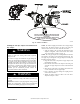
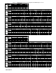
Rotate vent elbow to
required position.
Any other unused
knockout may be used
for combustion air
connection.
&
UPFLOW LEFT CONFIGURATION
A11309A
1
2
3
4
5
6
7
5
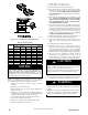
Rotate vent elbow to
required position.
A
ny other unused
knockout may be used
for combustion air
connection.
UPFLOW RIGHT CONFIGURATION
A11308A
1
2
3
4
5
6
7
5
A
ny other unused
knockout may be used
for combustion air
connection.
UPFLOW VERTICAL VENT
A11310A
Fig. 45 -- Upflow Configurations (Appearance may vary)
See “ Notes for Venting Options”
1
2
3
4
5
6
7
5
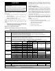
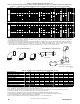
Rotate vent elbow to
required position.
DOWNFLOW LEFT CONFIGURATION
A11311A
1
2
3
4
5
6
7
5
Rotate vent elbow to
required position.
A
ny other unused
knockout may be used
for combustion air
connection.
DOWNFLOW RIGHT CONFIGURATION
A11312A
Requires Accessory Internal Vent Kit.
See Product Data for current kit number.
DOWNFLOW VERTICAL
A11313A
Fig. 46 -- Downflow Config urations (Appearance may vary)
See “ Notes for Venting Options”