
Installation Manual


440 01 4501 01 33
Specifications subject to change without notice.
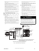
Table 11 – Electrical Data
FURNACE SIZE
V O LT S ---
H E R T Z ---
PHASE
OPERATING VOLTAGE
RANGE*
MAXIMUM
UNIT
AMPS
UNIT
AMPACITY#
MINIMUM
WIRE
SIZE
AWG
MAXIMUM
WIRE
LENGTH
FT (M)}
MAXIMUM
FUSE OR CKT
BKR
AMPS{
Maximum* Minimum*
0261410
1 1 5 --- 6 0 --- 1 127 104 5.1 7.3 14 50 (15.5) 15
0401410
1 1 5 --- 6 0 --- 1 127 104 7 9.7 14 38 (11.7) 15
0401712
1 1 5 --- 6 0 --- 1 127 104 7.5 10.3 14 36 (10.9) 15
0601412
1 1 5 --- 6 0 --- 1 127 104 7.1 9.8 14 38 (11.5) 15
0601714
1 1 5 --- 6 0 --- 1 127 104 9.6 12.9 14 28 (8.7) 15
0801716
1 1 5 --- 6 0 --- 1 127 104 10 13.4 14 27 (8.4) 15
0802120
1 1 5 --- 6 0 --- 1 127 104 12.3 16.3 12 35 (10.7) 20
1002120
1 1 5 --- 6 0 --- 1 127 104 12.6 16.6 12 34 (10.5) 20
1202420
1 1 5 --- 6 0 --- 1 127 104 12.4 16.4 12 35 (10.7) 20
1402422
1 1 5 --- 6 0 --- 1 127 104 12.6 16.6 12 34 (10.5) 20
* Permissible limits of the voltage range at which the unit operates satisfactorily.
# Unit ampacity = 125 percent of largest operating component’s full load amps plus 100 percent of all other potential operating components’ (EAC, humidifier,
etc.) full load amps.
{Time---delay type is recommended.
}Length shown is as measured one way along wire path between furnace and service panel for maximum 2 percent voltage drop.
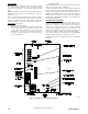
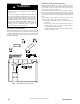
A190085
Fig. 37 -- Thermostat Wiring Diagrams
NOTES FOR THERMOSTAT WIRING DIAGRAMS
1. Refer to outdoor equipment Installation Instructions for additional information and setup procedure.
2. Outdoor Air Temperature Sensor must be attached in all dual fuel application.
3. Refer to ICP thermostat Installation Instructions for additional information and setup procedure.
4. HUM 24VAC terminal is 24 VAC and is energized when the low pressure switch closes during a call for heat.
5. When connecting 115 VAC to humidifier use a separate 115 VAC supply.
6. When using a humidifier on a HP installation, connect humidifier to hot water.
VENTING
NOTE: Planning for the venting system should be done in
conjunction with planning for the ductwork, drainage, and furnace
accessories, such as air cleaners and humidifiers. Begin assembling
the venting system AFTER the furnace is set in place in the
required orientation.
Venting for this furnace shall follow all Local codes for Category
IV venting systems. This furnace is CSA approved for venting
with PVC/ABS DWV venting systems. This furnace is also CSA
approved for venting with M&G DuraVentR PolyProR
polypropylene venting systems.
NOTE: THESE INSTRUCTIONS DO NOT CONTAIN
DETAILED INSTALLATION INSTRUCTIONS FOR